


6
Configure the VFD — All configurations required by
the VFD are supplied by the ICVC through the VFD Gateway.
Any configuration changes necessary and possible are made on
the ICVC screens. A complete set of configurations is transmit-
ted to the VFD each time the controls are powered up.
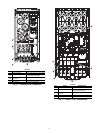
The following is from the 19XRV PIC III ICVC screen. Pa-
rameters in italics are to be entered or confirmed at start-up. Pa-
rameters in bold are to be changed only after consulting with
Carrier service engineering. See Table 2.
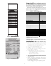
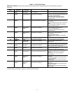
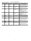
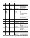
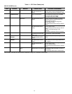
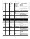
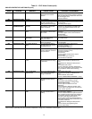
Table 2
— VFD Configurations
* Parameters marked with an * are not downloadable to the VFD but are used
in other calculations and algorithms in the ICVC.
NOTES:
1. Parameters in italics are to be entered or confirmed at start-up.
2. Parameters in bold are to be changed only after consultation with ser-
vice engineering.
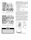
Commissioning the Unit — The commission proce-
dure is as follows:
1. If the chiller has been stored outdoors, allow at least 24
hours room temperature stabilization prior to commis-
sioning. Ensure any condensation that occurs as a result
of the ambient temperature is allowed to evaporate.
2. Enter parameters in the VFD_CONF screen.
3. Install surge suppression devices if required.
4. Review the power wiring and grounding to ensure that it
has been properly connected.
5. Visually examine the inside of the drive enclosure to:
a. Look for signs of corrosion or moisture residue.
b. Remove any dirt or debris.
c. Make sure all vents are clear.
6. Apply power to the drive and take thermal measurements
of the capacitor bank and power connections. Do this
again before start-up.
7. Measure and record the incoming line voltage. Line-to-
line voltages should be balanced within 3% as calculated
by Rockwell’s procedure below:
Measure voltages phase-to-phase and phase-to-ground.
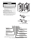
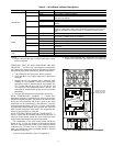
MODEL NUMBER
SERIAL NUMBER
VOLTS/PHASE/HERTZ
LOCKED ROTOR AMPS
OVERLOAD TRIP AMPS
MAX FUSE/CIRCUIT BREAKER SIZE
MIN SUPPLY CIRCUIT AMPACITY
MOTOR NAMEPLATE VOLTAGE
COMPRESSOR 100% SPEED
RATED LINE VOLTAGE
RATED LINE AMPS
RATED LINE KILOWATTS
MOTOR RATED LOAD KW
MOTOR RATED LOAD AMPS
MOTOR NAMEPLATE AMPS
MOTOR NAMEPLATE RPM
MOTOR NAMEPLATE KW
INTERTER PWM FREQUENCY
MACHINE NAMEPLATE SUPPLY DATA
MACHINE ELECTRICAL DATA
SAFETY CODE CERTIFICATION
THE COMPRESSOR MOTOR CONTROLLER AND OVERLOAD PROTECTION MUST BE
IN ACCORDANCE WITH CARRIER SPECIFICATION Z-420.
19XV05008701 REV. 3
A United Technologies Company
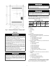
Fig. 8 — Machine Nameplate
a19-
1846
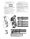
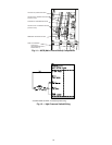
Fig. 9 — Drive Module Label
a19-
1924
PARAMETER DEFAULT VALUE
Motor Nameplate Voltage 460
Compressor 100% Speed
Line Freq=60 Hz? (No=50) Yes
Rated Line Voltage* 460
Rated Line Amps* 200
Rated Line Kilowatts * 100
Motor Rated Load kW* 100
Motor Rated Load Amps* 200
Motor Nameplate Amps 100
Motor Nameplate RPM 3456
Motor Nameplate KW 100
Inverter PWM Frequency (0 = 4 kHz, 1 =
2kHz)
1
Skip Frequency 1 (Hz) 102.0
Skip Frequency 2 (Hz) 102.0
Skip Frequency 3 (Hz) 102.0
Skip Frequency Band Line (Hz) 0.0
Voltage % Imbalance 10
Line Volt Imbalance Time (sec) 10
Line Current % Imbalance 40
Line Current Imbal Time (sec) 10
Motor Current % Imbalance 40
Motor Current Imbal Time 10
Increase Ramp Time (sec) 30
Decrease Ramp Time (sec) 30
Single Cycle Dropout (DSABLE/ENABLE) DSABLE