


5
START-UP
Alternate Wire Lugs —
In the case where the incoming
power wire size does not fit the standard lug, alternate lugs may
be used. See Table 1. Note that lugs rated for a higher current
than the circuit breaker may be used.
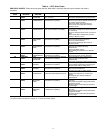
Table 1 — Wire Lugs
Verify Installation — Record the following job
information:
1. Job Name
2. Job Number
3. City
4. State
5. Zip Code
Record the following nameplate information:
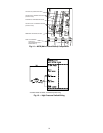
1. From the Allen-Bradley nameplate (Fig. 1) located inside
the VFD enclosure:
a. Allen-Bradley ID or CAT NO.
b. Allen-Bradley Serial Number
c. Carrier Part Number
2. From the machine nameplete (Fig. 8) located inside the
VFD enclosure:
a. Chiller Serial Number
b. Chiller Model
c. Motor rated load amps
d. Motor nameplate rpm
e. Motor nameplate kW
f. Motor nameplate voltage
g. IPWM (pulse width modulation) frequency
h. Voltage
3. From the drive module label (Fig. 9) located on the drive
module:
a. Model or Cat. Number
b. Serial Number
4. From the ICVC control panel screen:
a. Carrier Part Number and Revision
b. ICVC Software Number
Rockwell PowerFlex 750 drive start-up must be registered
on the Rockwell website. Rockwell Registration site URL:
http://www.automation.rockwell.com/warp/default.asp
DANGER
Internal components and circuit boards of the drive are live
when the drive is connected to incoming power. Coming
into contact with this voltage is extremely dangerous and
will result in severe personal injury or death.
The motor terminals U, V, W and the DC-link/brake resis-
tor terminals B+/R+, R- are live when the drive is con-
nected to incoming power, even if the motor is not running.
Do not make any connections when the drive is connected
to the incoming power.
After having disconnected the drive, wait until the indica-
tors on the keypad go out (if no keypad is attached see the
indicator through the keypad base). Wait 5 more minutes
before doing any work on drive connections. Do not even
open the cover before this time has expired..
Before connecting the drive to the incoming power, make
sure that the switchgear enclosure door is closed.
WARNING
The control I/O-terminals are isolated from the mains
potential. However, the relay outputs and other I/O termi-
nals may have a dangerous control voltage present even
when the drive is disconnected from incoming power.
Coming into contact with this voltage could result in severe
personal injury.
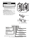
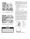
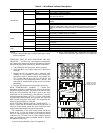
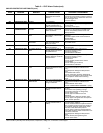
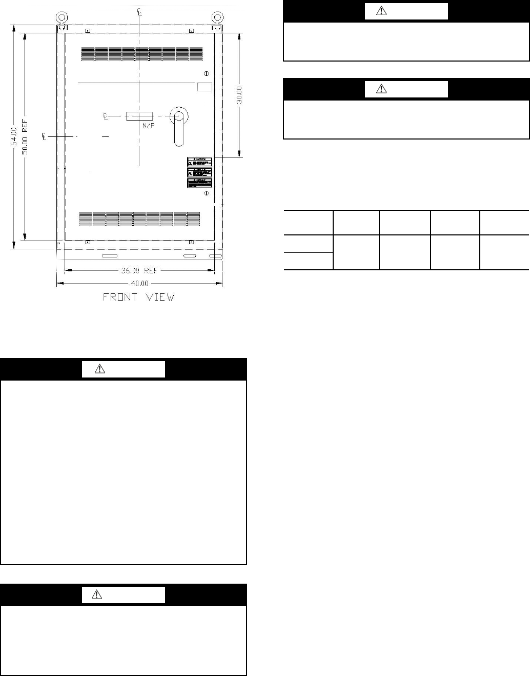
Fig. 7 — Enclosure Dimensions - Frames 6 and 7
A19-1834
CAUTION
If other than refrigerant cooling is used, before connecting
the drive to the incoming power, make sure that the coolant
is circulating and has no leaks.
CAUTION
When working with the Drive Explorer, never use the
Rotate function as the motor will immediately start and
severe compressor damage could result.
CIRCUIT
BREAKER
STANDARD
ABB LUG
STANDARD
LUG CABLE
RANGE
ALTERNATE
ABB LUG
ALTERNATE
LUG CABLE
RANGE
65 KAIC
(Standard)
K6TJ
(3) 2/0 - 400
MCM
K6TH
(2) 250 - 500
MCM
100 KAIC
(Optional)