


4
LEGEND
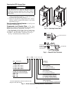
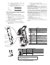
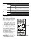
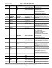
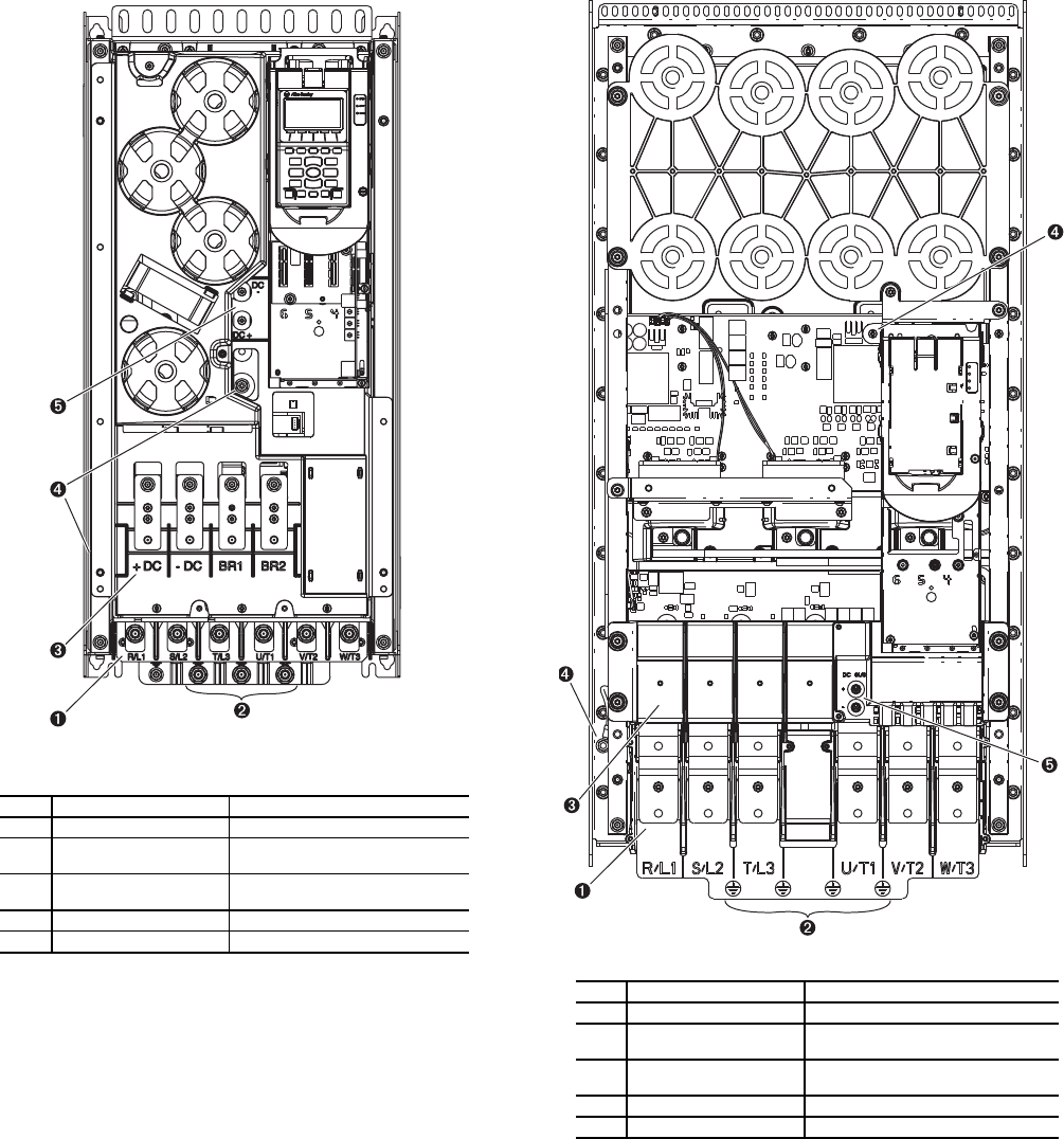
Fig. 5 — Frame 6 Drive Components
NO. NAME DESCRIPTION
1 Power Terminals R/L1, S/L2, T/L3, U/T1, V/T2, W/T3
2
PE Grounding Studs Terminating point to chassis ground
for incoming motor shield
3
DC Bus and Brake
Terminals
+DC, -DC, BR1, BR2
4 PE-A and PE-B MOV and CMC Jumper Wires
5 DC+ and DC- Bus Voltage Test Points
A19-
1832
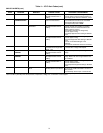
LEGEND
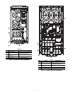
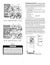
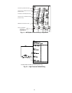
Fig. 6 — Frame 7 Drive Components
NO. NAME DESCRIPTION
1 Power Terminals R/L1, S/L2, T/L3, U/T1, V/T2, W/T3
2
PE Grounding Studs Terminating point to chassis ground
for incoming motor shield
3
DC Bus and Brake
Te rmi nal s
+DC, -DC, BR1, BR2
4 PE-A and PE-B MOV and CMC Jumper Wires
5 DC+ and DC- Bus Voltage Test Points
A19-1833