


23
Servicing the Drive
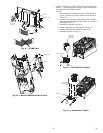
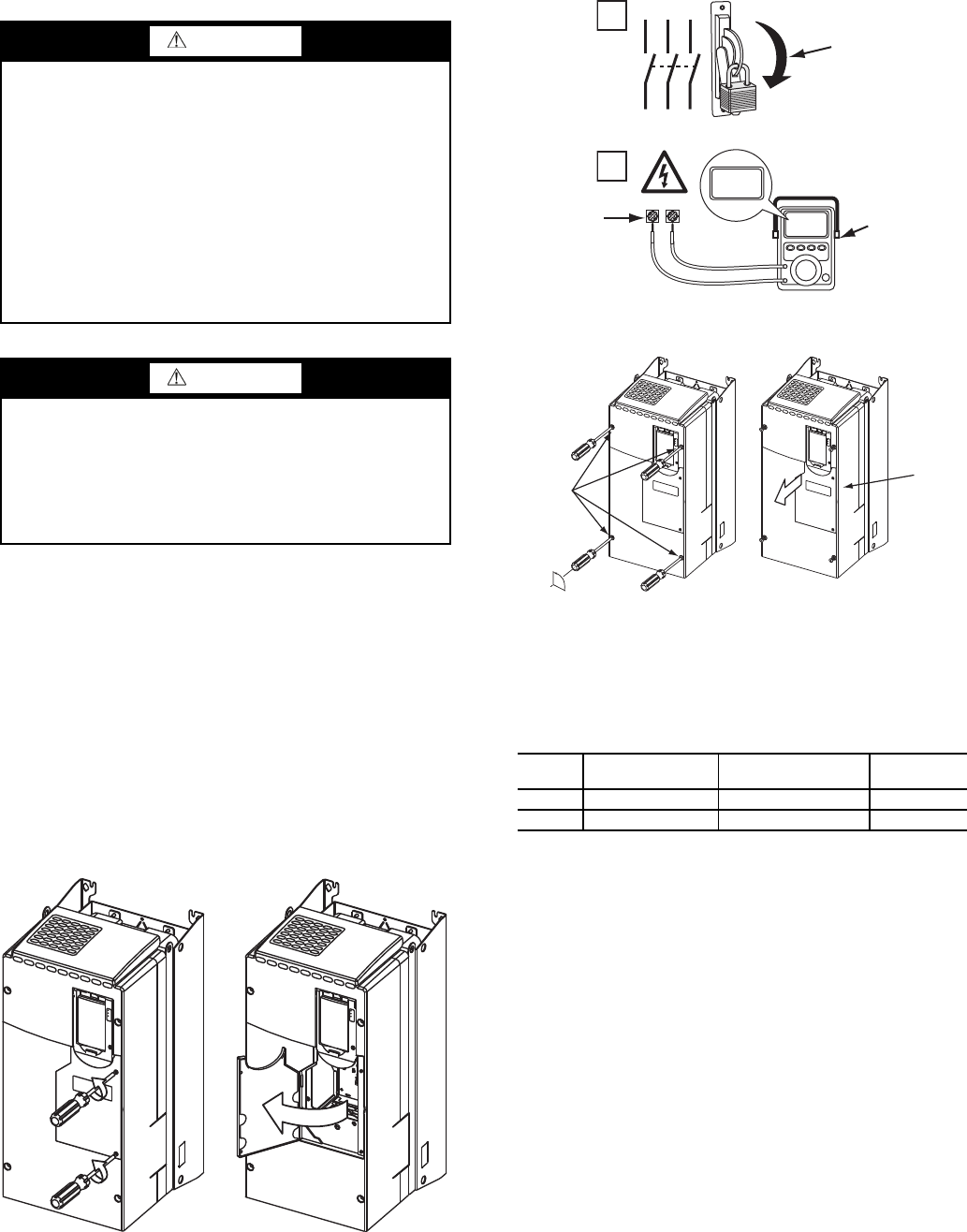
1. Using recommended screwdriver = 6.4 mm (0.25 in.) flat
or T20 star, open access door. See Fig. 16.
2. Check to be sure that the voltage between DC+ and DC-
and from each DC terminal to the chassis is zero before
proceeding. See Fig. 17.
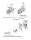
3. Remove the enclosure. See Fig. 18.
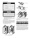
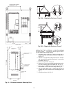
REMOVING THE DRIVE — The dimensions and weights
specified must be taken into consideration when removing the
drive. All lifting equipment and lifting components (hooks,
bolts, lifts, slings, chains, etc.) must be properly sized and rated
to safely lift and hold the weight of the drive while removing it.
See Fig. 19. The drive weights are as follows:
• Drive weight for Frame 6: 85 lb.
• Drive weight for Frame 7: 160 - 249 lb.
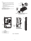
When replacing the drive, reverse the procedures and tight-
en to the torques for the Frames 6 and 7 Power Terminal Block
referred to in Table 8.
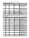
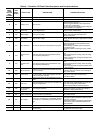
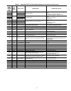
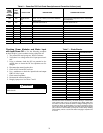
Table 8
— Frames 6 and 7 Power Terminal Block
RIGGING THE ENCLOSURE —
Where overhead room
and/or clearance in front of the drive enclosure is insufficient to
allow the drive to be safely removed from the enclosure, the
entire enclosure may have to be removed from the chiller.
The dimensions and weights specified must be taken into
consideration when removing the enclosure. The total weight
for Frames 6 and 7, including drive weight and enclosure, is
720 lb. All lifting equipment and lifting components (hooks,
bolts, lifts, slings, chains, etc.) must be properly sized and rated
to safely lift and hold the weight of the enclosure and drive
while removing. See Fig. 20A and Fig. 20B.
WARNING
To guard against possible personal injury and/or equipment
damage:
1. Inspect all lifting hardware for proper attachment be-
fore lifting drive.
2. Do not allow any part of the drive or lifting mecha-
nism to make contact with electrically charged con-
ductors or components.
3. Do not subject the drive to high rates of acceleration
or deceleration while transporting to the mounting lo-
cation or when lifting.
Do not allow personnel or their limbs directly underneath
the drive when it is being lifted and mounted.
WARNING
DC bus capacitors retain hazardous voltages after input
power has been disconnected. After disconnecting input
power, wait five (5) minutes for the DC bus capacitors to
discharge and then check the voltage with a voltmeter to
ensure the DC bus capacitors are discharged before touch-
ing any internal components. Failure to observe this pre-
caution could result in severe bodily injury or loss of life.
Fig. 16 — Open Access Door
A19-1831
FRAME
MAXIMUM LUG
WIDTH
RECOMMENDED
TORQUE
TERMINAL
BOLT SIZE
6 34.6 mm (1.36 in.) 11.3 N
·m (100 in.-lb) M8 x 1.25
7 43.5 mm (1.71 in.) 11.3 N
·m (100 in.-lb) M8 x 1.25
1
L1 L2 L3
O
I
2
DC+ DC–
0V
0V
LOCKOUT/TAGOUT
MULTIMETER
DC BUS TEST
TERMINALS
LOCATED INSIDE
ACCESS DOOR
Fig. 17 — Check DC Bus Terminals
A19-1814
90°
SLIDE
ENCLOSURE
FORWARD
LOOSEN
ENCLOSURE
FASTENERS
Fig. 18 — Removing Enclosure
A19-1816