


26
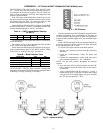
Frame 7:
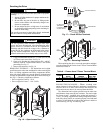
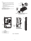
1. Disconnect power to the drive. Before removing the en-
closure, open the access door on the front of the drive.
See Fig. 16.
2. Check to be sure that the voltage between DC+ and DC-
and from each DC terminal to the chassis is zero before
proceeding. See Fig. 17.
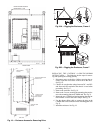
3. Remove the enclosure. See Fig. 18.
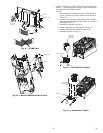
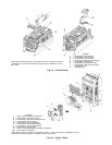
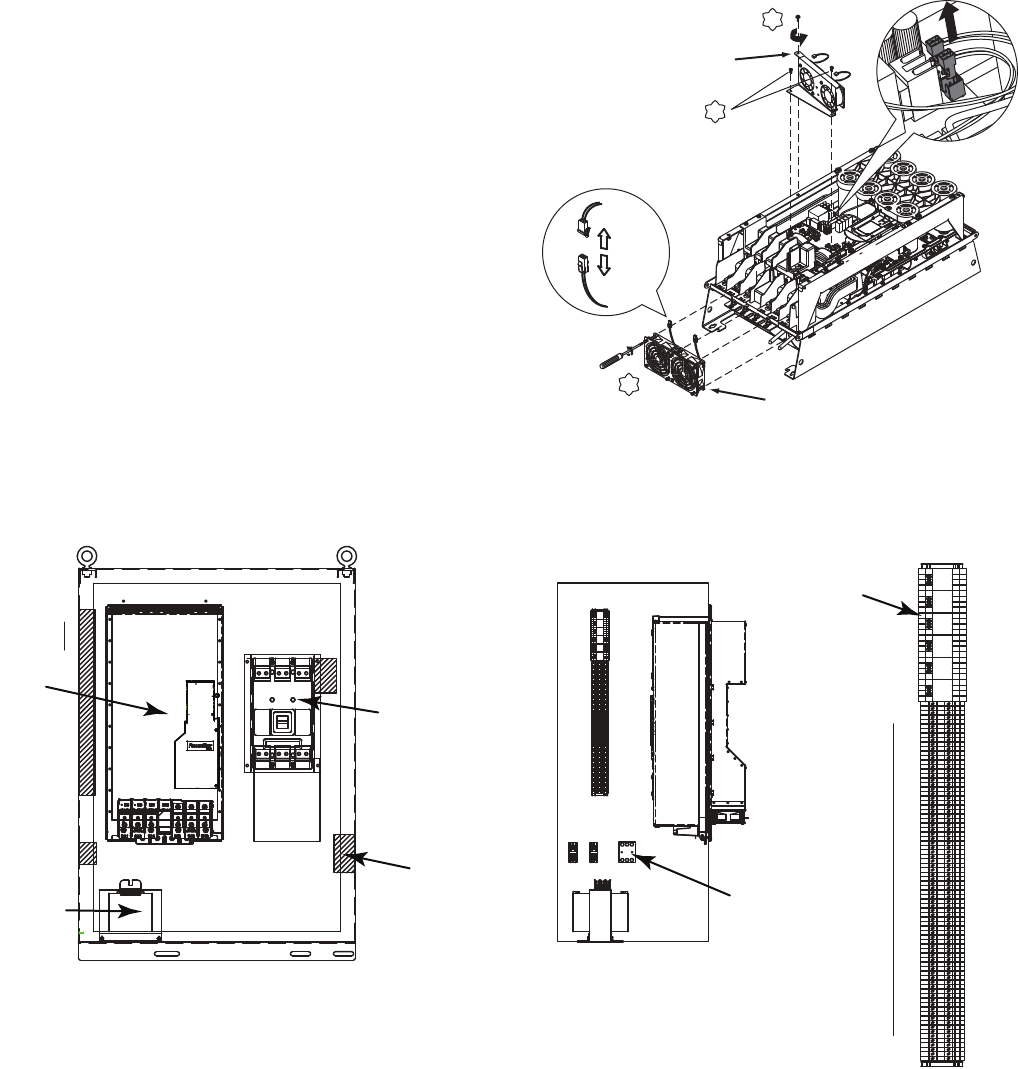
4. Remove and replace the Heat Sink and Internal and fans.
See Fig. 25.
Install the enclosure. See Fig. 18.
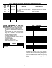
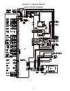
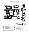
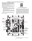
Part Identification and Location — See Fig. 26-28
for parts descriptions and locations.
X2
T20
5.20 N•m
(46 lb•in.)
T15
2.6 N•m (23 lb•in.)
T15
INTERNAL FANS
CHILL PLATE FANS
2.6 N•m (23 lb•in.)
Fig. 25 — Chill Plate and Internal Fans, Removal
and Replacement, Frame 7
A19-1841
3P
KTK/FNQ-R
30A
111
222
1 2 3 4 5 6
7 8
9 10 11 12 13
14
15 161718
19
2021 22 2324 25
TB4
26 2728293031
32 33
34 353637 38394041 42 4344
45 46
47 48495051 52
53
54 555657
58
59606162636465 666768697071
72 73
74 757677 787980
876 5
4 3 21
9
14
1211 10
13
CR1
876 5
4 3 21
9
14
1211 10
13
CR2
876 5
4 3 21
9
14
1211 10
13
CR3
876 5
4 3 21
9
14
1211 10
13
CR4
876 5
4 3 21
9
14
1211 10
13
CR5
876 5
4 3 21
9
14
12 11 10
13
CR6
EA1
CB1
CABLE
ACCESS
CUTOUT
SECONDARY SIDE
PT1
CB
1
2
34
5
678
91011 12
1314 15
16
17 18 19 20 21
22
2324
25
TB4
26 27
28 29 30
31
32
3334 35
36
37 38
39 40
4142
43
44 45
46 47
48 49 5051 52 53
54
55 56
57
58 59 6061 62 63
64
65 66 67 68 697071 72 7374
75
76
77 78
79
80
876
5
4
3
21
9
14
12 11
10
13
CR1
876
5
4
3
21
9
14
12 11
10
13
CR2
876
5
4
3
21
9
14
12 11
10
13
CR3
876
5
4
3
21
9
14
12 11
10
13
CR4
876
5
4
3
21
9
14
12 11
10
13
CR5
876
5
4
3
21
9
14
12 11
10
13
CR6
PT1
SECONDARY
SIDE
TOWARD
DOOR
CB2
FRONT VIEW
DOOR REMOVED
LEFT SIDEWALL
VIEW FROM INSIDE
1
80
LINE-
PE
6
5
3
2
4
1
TB1,TB2,
FU1-FU3
TB4
CR1
CR6
DIST.
SIDE
TB1 TB2
FU2
FU1 FU3
Fig. 26 — Assembly Parts
LEGEND
1—Power Module
2—Input Circuit Breaker
3—15 Amp Control Circuit Breaker
4—Control Transformer
5—Control Fuses
6—Control Relays (CR1 - CR5)
a19-1847