


3
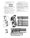
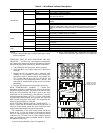
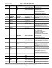
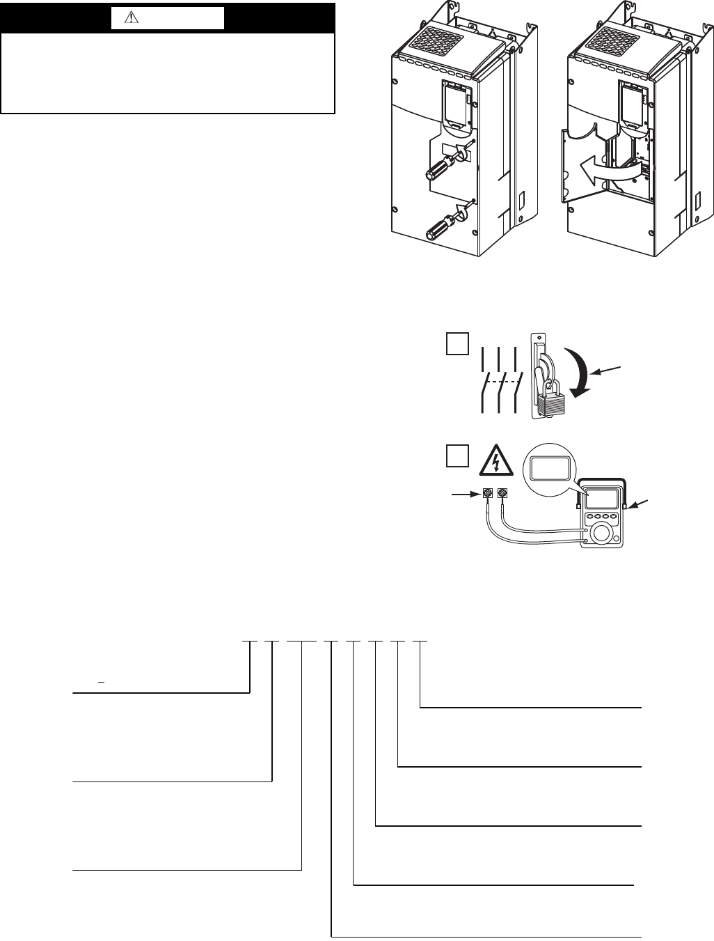
Opening the VFD Access Door
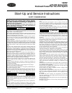
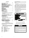
1. Using recommended screwdriver = 6.4 mm (0.25 in.) flat
or T20 star, open access door. See Fig. 2.
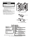
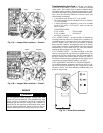
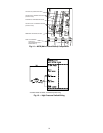
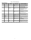
2. Check to be sure that the voltage between DC+ and DC-
and from each DC terminal to the chassis is zero before
proceeding. See Fig. 3.
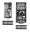
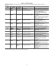
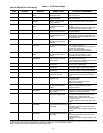
Drive Assembly Catalog Number — See Fig. 4 for
an example Catalog Number.
Components and Physical Data — The Allen-
Bradley PF755 Frame 6 drive is used for the 230-amp rated ap-
plication (carrier Part No. 19XRV0230...). See Fig. 5.
The Allen-Bradley PF755 Frame 7 drive is used for the
335-amp and 445-amp rated application (Carrier Part No.
19XVR0335... and 19XVR0445... respectively). See Fig. 6.
See Fig. 7 for the dimensions of Frames 6 and 7.
WARNING
Before removing the drive enclosure, open access door and
verify that the DC bus voltage has dropped to zero by
checking the terminals behind the access door. Failure to
observe this precaution could result in severe bodily injury
or loss of life.
Fig. 2 — Opening Access Door
A19-1831
1
L1 L2 L3
O
I
2
DC+ DC–
0V
0V
LOCKOUT/TAGOUT
MULTIMETER
DC BUS TEST
TERMINALS
LOCATED INSIDE
ACCESS DOOR
Fig. 3 — Check DC Bus Terminals
A19-1814
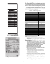
21P 1 0248 3 - 3 -0-0 C-
21P PF755 VFD
Voltage Rating
1
2
3
Customer
C –Carrier
Meter Package
0 – No Meter Package
1 –Analog Meter Package
– 460 to 480 v, 60 Hz
– 380 to 415 v, 50 Hz
– 380 to 400 v, 60 Hz
4
PF755 Full Load Amp Rating
(Maximum Continuous Amps)*
0248 – 248
0361 – 361
0477
477
Disconnect/Breaker Options
3
65 KAIC Capacity Breaker
Input Reactor
0 – No Input Reactor
1 – 3% Input Line Reactor
– 401 to 439 v, 60 Hz
0477
–
477
3
–
65
KAIC
Capacity
Breaker
4 – 100 KAIC Capacity Breaker
Drive Assembly
3 – Unit Mount NEMA 1 Liquid Cooled
Fig. 4 — Drive Assembly Catalog Number Nomenclature
A19-1842
* For Carrier applications, maximum continuous amp
ratings are 230, 335, and 445.