


2
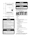
CONTENTS
Page
SAFETY CONSIDERATIONS . . . . . . . . . . . . . . . . . . . . . . 1
INTRODUCTION . . . . . . . . . . . . . . . . . . . . . . . . . . . . . . . . . . 2
ABBREVIATIONS AND EXPLANATIONS . . . . . . . . . . 2
Required Publications. . . . . . . . . . . . . . . . . . . . . . . . . . . . 2
Getting Assistance from Rockwell Automation . . . 2
IDENTIFYING DRIVE COMPONENTS. . . . . . . . . . . . 2-5
Opening the VFD Access Door . . . . . . . . . . . . . . . . . . . 3
Drive Assembly Catalog Number . . . . . . . . . . . . . . . . . 3
Components and Physical Data . . . . . . . . . . . . . . . . . . 3
START-UP . . . . . . . . . . . . . . . . . . . . . . . . . . . . . . . . . . . . . . 5-8
Alternate Wire Lugs . . . . . . . . . . . . . . . . . . . . . . . . . . . . . . 5
Verify Installation. . . . . . . . . . . . . . . . . . . . . . . . . . . . . . . . . 5
Configure the VFD. . . . . . . . . . . . . . . . . . . . . . . . . . . . . . . . 6
Commissioning the Unit. . . . . . . . . . . . . . . . . . . . . . . . . . 6
Check Internal Jumpers . . . . . . . . . . . . . . . . . . . . . . . . . . 7
SERVICE . . . . . . . . . . . . . . . . . . . . . . . . . . . . . . . . . . . . . . 8-27
Troubleshooting the Drive. . . . . . . . . . . . . . . . . . . . . . . . 8
• ICVC ALERT CODES
• ICVC ALARM CODES
• TEST EQUIPMENT NEEDED TO TROUBLESHOOT
• VERIFYING THAT DC BUS CAPACITORS ARE
DISCHARGED
• HIGH TEMPERATURE ALARMS
• MAIN CONTROL BOARD (MCB) COMPONENTS
Checking Power Modules and Motor Input
with Input Power Off . . . . . . . . . . . . . . . . . . . . . . . . . . 22
Servicing the Drive . . . . . . . . . . . . . . . . . . . . . . . . . . . . . . 23
• REMOVING THE DRIVE
• RIGGING THE ENCLOSURE
• REPLACING THE GATEWAY (A-B20-750-20COMM
OPTION CARD)
• CHILL PLATE FAN AND INTERNAL FAN
REPLACEMENT
Parts Identification and Location . . . . . . . . . . . . . . . . 26
APPENDIX A — WIRING SCHEMATICS . . . . . . . 28-31
APPENDIX B — OPTIONAL BACNET
COMMUNICATIONS WIRING . . . . . . . . . . . . . . . 32-38
INTRODUCTION
The Carrier VFD option Start-Up and Service Manual is in-
tended for trained and qualified service personnel, and is to be
used during start up, operation, and maintenance of Rockwell/
Allen-Bradley PF755L drive.
ABBREVIATIONS AND EXPLANATIONS
Frequently used abbreviations in this manual include:
Required Publications — The Carrier VFD option
Start-Up and Service Manual must be used with the following
manuals:
• The latest version of the PowerFlex 750-Series AC
Drives manuals
• The latest revision of the Start-Up, Operation, and Main-
tenance Instructions for the 19XRV with PIC III Controls
Getting Assistance from Rockwell Automa-
tion — Contact the local Rockwell Automation sales office
with any questions or problems relating to the products de-
scribed in this manual. For technical support on drives between
the hours of 7:00 am and 6:00 pm CST, M-F, call 1-262-512-
8176. For information about after-hours phone support and on-
site support call 1-800-800-0522.
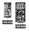
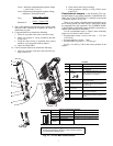
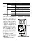
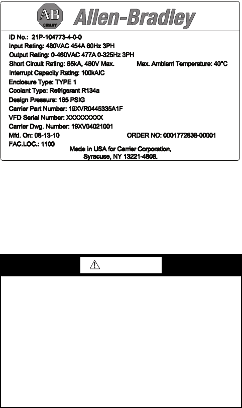
Before calling, have the following information available
from the Allen-Bradley data nameplate located inside the en-
closure on the right wall. See Fig. 1.
• Allen-Bradley ID or CAT. NO.
• Carrier VFD Code
• Allen-Bradley serial number
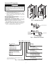
IDENTIFYING DRIVE COMPONENTS
A chiller control schematic and a VFD schematic are in-
cluded in Appendix A.
CCM — Chiller Control Module
DC — Direct Current
DPI — Drive Peripheral Interface
ENET — Ethernet
ICVC — International Chiller Visual Controller
IGBT — Insulated Gate Bipolar Transistor
I/O — Inputs/Outputs
IP — Internet Protocol
IPWM — Inverter Pulse Width Modulation
MCB — Main Control Board
MOV — Metal Oxide Varistor
PE — Protective Earthing Conductor
SIO — Sensor Input/Output
STS — Status
WARNING
DC bus capacitors retain hazardous voltages after input
power has been disconnected. After disconnecting input
power, wait five (5) minutes for the DC bus capacitors to
discharge and then check the voltage with a voltmeter rated
for the DC bus voltage to ensure the DC bus capacitors are
discharged before touching any internal components. Fail-
ure to observe this precaution could result in severe bodily
injury or loss of life.
An isolated multimeter will be needed to measure DC bus
voltage and to make resistance checks. The drive’s DC bus
capacitors retain hazardous voltages after input power has
been disconnected.
Fig. 1 — Allen Bradley Data Nameplate
A19-1830
711