


16
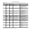
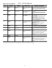
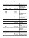
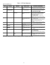
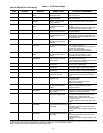
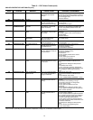
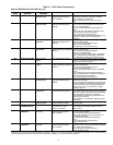
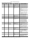
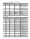
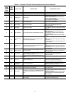
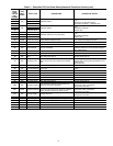
Table 5 — ICVC Alarm Codes (cont)
CHILLER PROTECTIVE LIMIT FAULTS (cont)
*[LIMIT] is shown on the ICVC as the temperature, pressure, voltage, etc., set point predefined or selected by the operator as an override, alert, or
alarm condition. [VALUE] is the actual pressure, temperature, voltage, etc., at which the control tripped.
ICVC FAULT
STATE
PRIMARY
MESSAGE
SECONDARY
MESSAGE
PRIMARY CAUSE ADDITIONAL CAUSE/REMEDY
220 PROTECTIVE LIMIT GROUND FAULT 220Ground Fault Trip;
Check Motor and Current
Sensors.
Check for condensation on motor terminals.
Check motor power leads for phase to phase or
phase to ground shorts. Disconnect motor from
VFD and megger motor.
Call Carrier Service.
221 PROTECTIVE LIMIT UNUSED 221UNUSED
222 PROTECTIVE LIMIT LINE FREQUENCY TRIP 222Line Frequency —
[VALUE] exceeded limit of
[LIMIT]; Check Power Supply.
If operating from a generator, check generator
size and speed.
Check utility power supply.
223 LOSS OF
COMMUNICATION
WITH VFD GATEWAY
MODULE
223Loss of SIO Comm with
VFD Gateway: Check VFG
Module and Power.
Check VFD communication wiring and
connectors on VFD Gateway and DPI board.
Check for compatibility between ICVC and
Gateway software.
224 PROTECTIVE LIMIT VFD COMMUNICATIONS
FAULT
224Loss of DPI Comm with
VFD Gateway: Check VFG to
VFD Comm.
Check VFD communication wiring and
connectors.
Check status lights on DPI Communications
Interface Board.
Call Carrier Service.
225 PROTECTIVE LIMIT MOTOR CURRENT
IMBALANCE
225Motor Current Imbal-
ance: Check VFD Fault
History for Values.
Check Motor Current % Imbalance in
VFD_CONF screen.
226 PROTECTIVE LIMIT LINE PHASE REVERSAL 226Line Phase Reversal:
Check Line Phases.
Reverse connections of any two line conductors
to circuit breaker.
227 PROTECTIVE LIMIT OIL PRESS SENSOR
FAULT
227Oil Pressure Delta P
[VALUE] (Pump Off): Check
Pump/Transducers.
Check transducer wiring and accuracy.
Check power supply to pump.
Check pump operation.
Check transducer calibration.
228 PROTECTIVE LIMIT LOW OIL PRESSURE 228Low Operating Oil
Pressure [VALUE]: Check Oil
Pump and Filter.
Check transducer wiring and accuracy.
Check power supply to pump.
Check pump operation.
Check oil level.
Check for partially closed service valves.
Check oil filters.
Check for foaming oil at start-up.
Check transducer calibration.
229 PROTECTIVE LIMIT LOW CHILLED WATER
FLOW
229Low Chilled Water Flow;
Check Switch/Delta P Config
& Calibration.
Perform pump control test.
Check optional transducer calibration and
wiring.
Check Evaporator Refrigerant Temperature
sensor.
Check chilled water valves.
Check for evaporator saturation temperature
< 34 F if not in Pumpdown Lockout mode. Place
unit in Pumpdown mode before removing
charge.
230 PROTECTIVE LIMIT LOW CONDENSER
WATER FLOW
230Low Condenser Water
Flow; Check Switch/Delta P
Config & Calibration.
Perform pump control test.
Check optional transducer calibration and
wiring.
Check condenser water valves.
Check for COND PRESS OVERRIDE + 5 psig.
231 PROTECTIVE LIMIT HIGH DISCHARGE TEMP 231Comp Discharge Temp
[VALUE] Exceeded Limit of
[LIMIT]*.
Check for closed compressor discharge isola-
tion valve.
Check if chiller was operating in surge.
Check sensor resistance or voltage drop.
Check for proper wiring.
Check for proper condenser flow and
temperature.
Check compressor discharge isolation valve.
Check for proper inlet guide vane and optional
diffuser actuator operation.
232 PROTECTIVE LIMIT LOW REFRIGERANT
TEMP
232Evaporator Refrig Temp
[VALUE] exceeded limit of
[LIMIT]*.
Check for proper refrigerant charge.
Check float valve operation.
Check for closed condenser liquid line isolation
valve. If problem occurs at high load, check for
low condenser pressure which causes inade-
quate flasc orifice differential pressure.
Check for proper water flow and temperature.
Confirm that condenser water enters bottom row
of condenser tubes first.
Check Evaporator Refrigerant Temperature
sensor.
Check for division plate gasket bypass.
Check for fouled tubes.