


27
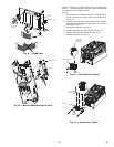
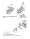
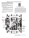
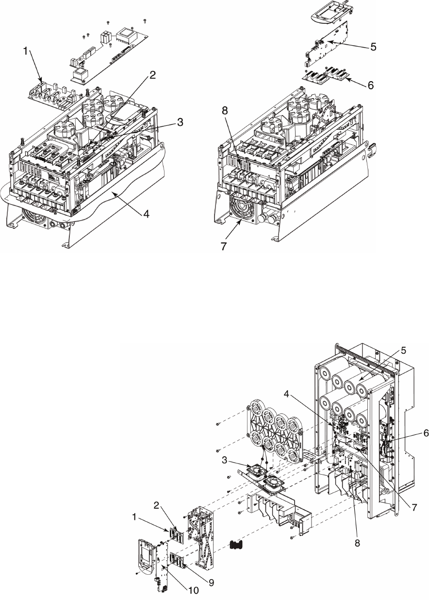
LEGEND
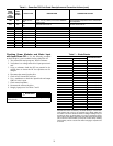
1—PF750 Series, Precharge Kit
2—PF750 Series, Gate Interface
3—PF750 Series, Power Interface
4—PowerFlex 750 Series, Flange Gasket
5—PF755 Main Control Board
6—PF750 Series, Backplane Interface
7—PF750 Series, Type 4X/12 Chill Plate
(Heatsink) Fan Kit
8 — Chill Plate Fan
NOTE: When replacing the Main Control Board (Item No. 1) the jumper marked
“J1 ENABLE” must be removed and the jumper marked “J1 SAFETY” must be
left in place.
a19-1848
Fig. 27 — Frame 6 Parts
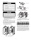
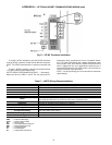
Fig. 28 — Frame 7 Parts
LEGEND
NOTE: When replacing the Main Control Board (Item No. 1) the jumper marked “J1 ENABLE” must be
removed and the jumper marked “J1 SAFETY” must be left in place.
1—Slot for Gateway (Gateway Not Shown)
2—PF750 Series, Backplane Interface
3—PF750 Series, Type 4X/12 Heatsink Fan Kit
4—PF750 Series, Power Interface
5—PF750 Series, Bus Cap Assembly
6—PF750 Series, Power Interface Cable
7—PF750 Series, Current Transducer Kit
8 — PF750 Series, Precharge Kit
9—Slot for 24V I/O Module (24V I/O Module Not Shown)
10 — PF755 Main Control Board
a19-1849