


31
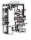
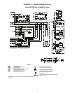
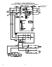
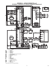
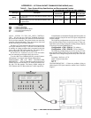
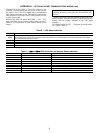
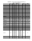
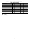
APPENDIX A — WIRING SCHEMATICS (cont)
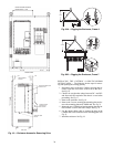
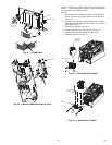
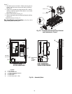
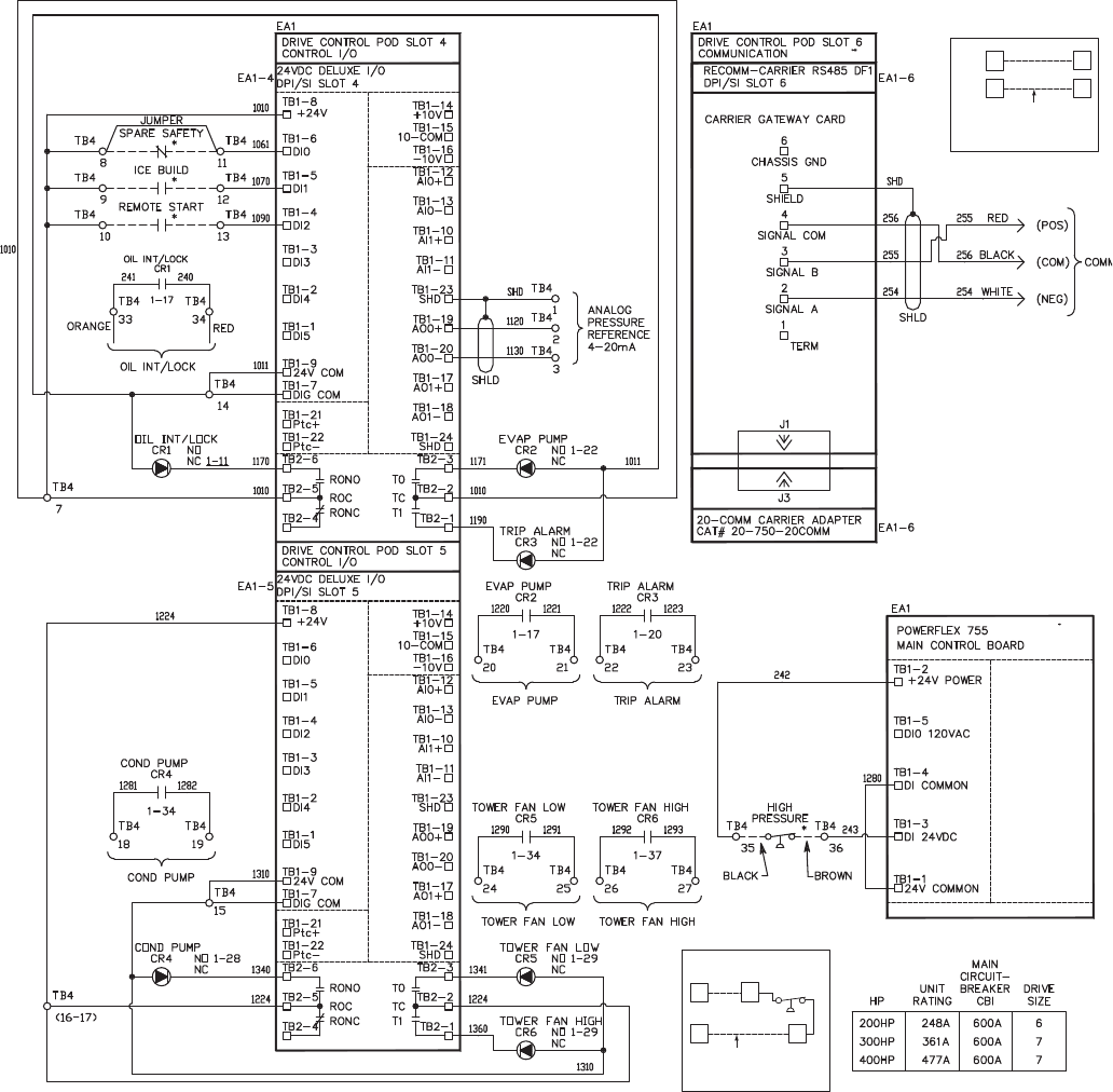
ROCKWELL POWERFLEX 755 WIRING SCHEMATIC (Typical) (cont)
3434
3333
TB4
TB4
CARRIER
F
ACTORY
WIRING
DETAIL A
SEE
DETAIL
A
3535
3636
TB4
TB4
CARRIER
F
ACTORY
WIRING
DETAIL B
POWER
PANEL
POWER
PANEL
SEE
DETAIL
B
43
19
a19-1967
LEGEND
CAP — Capacitor
CB — Circuit Breaker
COM — Common
COMM — Communication
COND — Condenser
CR — Control Relay
DPI/SI — Internal Communication Protocols Connections
EA — Electrical Assembly
EMI — Electro-Magnetic Interference
EVAP — Evaporator
FU — Fuse
GND — Ground
JMPR — Jumper
M—Motor
NC — Normally Closed
NO — Normally Open
PE — Potential Earth (Ground)
POD — I/O Card Mounting Slot Board
REM — Remote
ROC — Relay Output Common
SHLD — Shield
TB — Terminal Block
* Located outside of starter; connected by field wiring.
611