


9
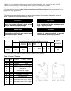
Table 4: Maximum Capacity of Schedule 40 Pipe in CFH of Natural Gas For Gas Pressures of 0.5 psig or Less
Table 5: Fitting Equivalent Lengths
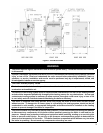
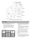
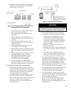
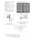
Figure 6: Recommended Gas Piping
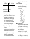
Table 6: Specic Gravity Correction Factors for
Natural Gas
2. Use thread (joint) compounds (pipe dope) resistant
toactionofliqueedpetroleumgas.
3. Install sediment trap, ground-joint union and manual
shut-off valve upstream of boiler gas control valve
and outside jacket. See Figure 6.
4. All above ground gas piping upstream from manual
shut-off valve must be electrically continuous and
bonded to a grounding electrode. Do not use gas
piping as grounding electrode. Refer to National
Electrical Code, ANSI/NFPA 70.
C. Pressure test. The boiler and its gas connection must be
leak tested before placing boiler in operation.
1. Protect boiler gas control valve. For all testing over
½ psig, boiler and its individual shutoff valve must
be disconnected from gas supply piping. For testing
at ½ psig or less, isolate boiler from gas supply
piping by closing boiler's individual manual shutoff
valve.
2. Locate leaks using approved combustible gas
detector,soapandwater,orsimilarnonammable
solution.Donotusematches,candles,openames,
or other ignition source.
Length
[Feet]
0.3 inch w.c. Pressure Drop 0.5 inch w.c. Pressure Drop
½ ¾ 1 1¼ ½ ¾ 1 1¼
10 132 278 520 1,050 175 360 680 1,400
20 92 190 350 730 120 250 465 950
30 73 152 285 590 97 200 375 770
40 63 130 245 500 82 170 320 660
50 56 115 215 440 73 151 285 580
60 50 105 195 400 66 138 260 530
70 46 96 180 370 61 125 240 490
80 43 90 170 350 57 118 220 460
90 40 84 160 320 53 110 205 430
100 38 79 150 305 50 103 195 400
Fitting
Nominal Pipe Size
½ ¾ 1 1¼
45° Ell 0.7 1.0 1.2 1.6
90° Ell 1.6 2.1 2.6 3.5
Tee
(As Elbow)
3.1 4.1 5.2 6.9
Specic Gravity Multiplier
0.55 1.40
0.60 1.00
0.65 0.96
0.70 0.93
0.75 0.90
0.80 0.87