


11
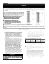
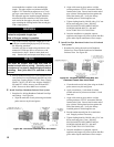
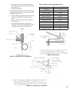
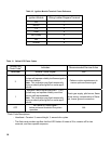
Table 8: Burnham Vent System Components
Part 11 in the National Fuel Gas Code, NFPA 54/
ANSI Z223.1.
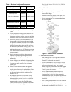
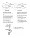
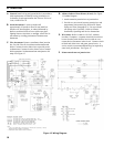
C. Install Vent Connector.
1. Remove vent connector from vent accessory carton.
2. Removegaskets,oriceplateandhardwarefrom
bloweroutletange.
3. Assembleoriceplategaskets,oriceplate,and
vent connector. See Figure 7.
4. Secure vent connector with washers and locknuts.
Do not overtighten.
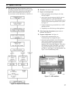
1. Seal any unused openings in the common venting
system.
2. Visually inspect the venting system for proper size
and horizontal pitch and determine there is no
blockage or restriction, leakage, corrosion, and other
deciencieswhichcouldcauseanunsafecondition.
3. Insofar as is practical, close all building doors and
windows and all doors between the space in which
the appliances remaining connected to the common
venting system are located and other spaces of the
building. Turn on clothes dryers and any appliance
not connected to the common venting system. Turn
on any exhaust fans, such as range-hoods and
bathroom exhausts, so they will operate at maximum
speed. Do not operate a summer exhaust fan. Close
replacedampers.
4. Place in operation the appliance being inspected.
Follow the Lighting (or Operating) Instructions.
Adjust thermostat so appliance will operate
continuously.
5. Test for spillage at the drafthood relief opening after
5minutesofmainburneroperation.Usetheame
of a match or candle, or smoke from a cigarette,
cigar or pipe.
6. After it has been determined that each appliance
remaining connected to the common venting system
properly vents when tested as outlined above, return
doors,windows,exhaustfans,replacedampersand
any other gas burning appliance to their previous
conditions of use.
7. Any improper operation of the common venting
system should be corrected so the installation
conforms with the National Fuel Gas Code, NFPA
54/ANSI Z223.1. When resizing any portion of the
common venting system, the common venting
system should be resized to approach the minimum
size as determined using the appropriate tables in
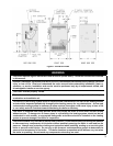
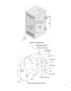
Figure 7: Vent Connector Installation
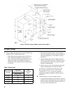
D. Install Vent Pipe, General.
1. Plan venting system to avoid possible contact with
plumbing or electrical wires. Start at vent
connector. Work toward vent terminal.
2. Use non-combustible ¾ inch pipe strap to support
horizontal runs and maintain vent location and slope
while preventing sags in pipe. Do not restrict
thermal expansion or movement. Maximum support
spacing is 5 feet. Do not penetrate any part of the
venting system with fasteners.
3. Provide and maintain minimum clearances to
combustible materials. Use single wall thimble
(Burnham Part No. 8116116) when penetrating
combustible wall. Other wall thimble manufacturers
are American Metal Products, Hart & Cooley, and
Metal Fab.
4. Once a vent pipe manufacturer and system is chosen
never mix and match vent systems.
5. If a non-standard length pipe is required, the use of
the adjustable length pipe (P/N 8116319U) is
Vent System
Component
Part
Number
Equivalent
Feet of Pipe
3" Dia. Pipe x 1 Ft 8116296U 1
3" Dia. Pipe x 3 Ft 8116298U 3
3" Dia. Pipe x 5 Ft 8116300U 5
3" Dia. Pipe x Adjustable 8116319U
Equal to
Installed Length
(1.1 to 1.7)
3" Dia. 90° Elbow 8116294U 5
3" Dia. 45° Elbow 8116292U 5
3" Dia. Horizontal Drain Tee 8116302U ½
3" Dia. Vertical Drain Tee 8116304U 7½
3" Single Wall Thimble 8116116 ---
3" Double Wall Thimble 8116115 ---