


2
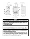
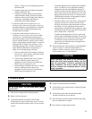
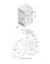
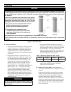
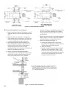
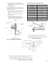
Figure 2: Tapping Locations
Table 2: Purpose of Tappings
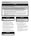
Table 1: Dimensions and Clearances
The following terms are used throughout this manual to bring attention to the presence of hazards of various risk
levels, or to important information concerning product life.
The New York City Department of Buildings has approved the Independence® PV boiler: Approval No. MEA 154-93-E.
The City of New York requires a Licensed Master Plumber supervise the installation of this product.
The Massachusetts Board of Plumbers and Gas Fitters has approved the Independence® PV boiler. See the Massachusetts Board
of Plumbers and Gas Fitters website, http://license.reg.state.ma.us/pubLic/pb_pre_form.asp for the latest Approval Code or
ask your local Sales Representative.
The Commonwealth of Massachusetts requires this product to be installed by a Licensed Plumber or Gas Fitter.
DANGER
Indicates an imminently hazardous situation
which, if not avoided, will result in death, serious
injury or substantial property damage.
WARNING
Indicates a potentially hazardous situation which,
if not avoided, could result in death, serious injury
or substantial property damage.
CAUTION
Indicates a potentially hazardous situation which,
if not avoided, may result in moderate or minor
injury or property damage.
NOTICE
Indicates special instructions on installation,
operation, or maintenance which are important
but not related to personal injury hazards.
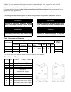
Boiler Model
Dimensions [inches]
Minimum Clearances from Combustible Materials [inches]
Approx.
Shipping
Weight Lbs.
(A) Width
(B) Flue
Connector
Left
Side
Right
Side
Front Rear Top Vent
PIN3PV 14-1/2 4
18 6 Alcove 6 12 *
355
PIN4PV 17-3/4 8-1/4 425
PIN5PV 21 9-1/4 490
PIN6PV 24-1/4 9-1/4 560
* Vent pipe minimum clearance to combustible material is ve (5) inches when vent is installed in a fully enclosed (chase) application or
four (4) inches when vent is installed with at least one side open, similar to a joist bay application.
Tapping Size PIN3PV PIN4PV - PIN6PV
A 2 Supply Plugged
B 2 Plugged Supply
C ½ Pressure Gauge (with ½ x ¼ bushing)
D 2 Drain Valve (with 2 x ¾ bushing)
E ¾ Safety Valve
F 1 Surface Blow-Off, Plugged
G ½ Gauge Glass
H ¾ Limit (with ¾ x ¼ bushing)
L ¾ Low Water Cut-Off
M 1¼ Indirect Water Heater Return, Plugged
N 1¼ Indirect Water Heater Supply, Plugged
P ¾ Indirect Water Heater Control, Plugged
R 2 Return