


16
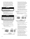
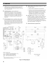
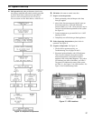
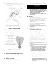
Figure 15: Wiring Diagram
VI. Electrical
A. General Install wiring and ground boiler in accordance
with requirements of authority having jurisdiction, or
in absence of such requirements the National Electrical
Code, ANSI/NFPA 70.
B. Install thermostat. Locate on inside wall
approximately4feetaboveoor.Donotinstallon
outsidewall,nearreplace,orwhereinuencedby
draftsorrestrictedairow,hotorcoldwaterpipes,
lightingxtures,television,orsunlight.Allowfreeair
movement by avoiding placement of furniture near
thermostat.
C. Wire thermostat. Remove transformer from junction
box. Provide Class II circuit between thermostat and
boiler. Connect circuit to blue wires to provide power
to thermostat. Connect circuit to brown wire to control
boiler operation. Set thermostat heat anticipator to 0.4
amps. See Figure 15.
D. Alliance Indirect Water Heater (if used) See Figure
15, Ladder Diagram.
1. Attach extension junction box to junction box.
2. Provide two wire circuit between junction box and
temperature limit control (See Section III: Steam
Piping and Trim, Paragraph E.2). Use one red and
one orange wire if possible. Refer to Alliance
Installation, Operating and Service Instructions.
E. Wire boiler. Boiler is rated for 120 VAC, 60 hertz,
less than 12 amperes. A separate electrical circuit must
be run from the main electrical service with an over-
current device/disconnect in the circuit. Connect circuit
to black and white wires and green ground screw. A
service switch is recommended and may be required by
some local jurisdictions. See Figure 15.
F. Mount transformer on junction box.