


12
a. Clean the male end of each joint using an alcohol
pad to remove any dirt and grease.
b. Apply a continuous ¼ inch bead of sealant
around male end of joint no more than 1/8 inch
from end.
c. Align weld seams in pipes and use a slight
twisting motion to FULLY insert male end into
female end of joint. Ensure bead in male end of
pipe is below locking band and rest against the
end of the female pipe. Verify the factory-
installed gasket is not dislodged or cut.
d. Smooth sealant around joint for a continuous
seal. Reapply sealant if necessary.
e. Tighten locking band by HAND with a 5/16" nut
driver until snug plus ¼ turn. DO NOT
SECURE JOINTS WITH SHEET METAL
SCREWS OR POP RIVETS. DO NOT
PUNCTURE THE VENT SYSTEM!
f. Once the installation is complete, operate
applianceandinspectalljointstoensurethatue
gases and/or liquid condensate will not escape.
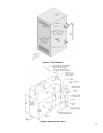
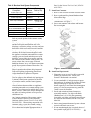
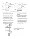
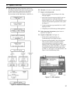
Figure 8A: Burnham Gasketed Vent Joint Detail
Figure 8B: Burnham Gasket-Less Male and
Gasketed Female Vent Joint Detail
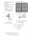
recommended to complete a non-standard pipe
length. This pipe requires a minimum installed
length of 12¾ inch and can adjust across a 7 inch
gap up to a maximum of 19¾ inch long. (Note for
the adjustable pipe the installed length should be
measured from the centerline of the bead on the
maleendoftherstpipetotheendofthefemale
pipe excluding the locking band of the second pipe
with a single gasket.)
WARNING
Never exceed maximum installed length of 19¾
inches for adjustable length pipe.
Risk of ue gas leakage is possible.
Only in the event the adjustable length pipe is not
sufcientastandardlengthpipemaybecutusing
the following procedure.
Carefully cut pipe to length using a hacksaw with
minimum 32 teeth per inch or circular saw with
metal abrasive wheel. Remove male (bead) end
only–female(bell)endacceptsnextttingorpipe.
NOTICE
Cut must be square with pipe and led or
sanded smooth before joining. Carefully ensure
roundness of cut pipe by hand with gloves before
installing. Seal joint with RTV specied in this
manual.
6. Seal all Burnham Gasket-Less vent, Burnham mixed
vent(Gasket-LessandGasketed)andeldcutjoints
using Dow Corning Silastic 732 RTV, Dow Corning
Silastic 736 RTV, GE RTV106, Polybac #500 RTV,
Sil-bond RTV 4500 (Acetoxy) and Sil-bond RTV
6500. Do not use other adhesives or sealants.
E. Install Vent Pipe, Burnham Gasketed Vent System.
1. Procedure for Joining Burnham Gasketed Vent Pipe
and Fittings. See Figure 8A.
a. Wipe the male end of each joint using an alcohol
pad to remove any dirt and grease.
b. Align weld seams in pipes and use a slight
twisting motion to FULLY insert male end into
female end of joint. Ensure bead in male end of
pipe is below locking band and rest against the
end of the female pipe. Verify the factory-
installed gasket is not dislodged or cut.
c. Tighten locking band by HAND with a 5/16" nut
driver until snug plus ¼ turn. DO NOT
SECURE JOINTS WITH SHEET METAL
SCREWS OR POP RIVETS. DO NOT
PUNCTURE THE VENT SYSTEM!
d. Once the installation is complete, operate
applianceandinspectalljointstoensurethatue
gases and/or liquid condensate will not escape.
F. Install Vent Pipe, Burnham Gasket-Less & Gasketed
Vent System.
1. Procedure for joining the male end of Burnham
Gasket-Less Vent with the female end of Burnham
Gasketed Vent. See Figure 8B.