


17
VII. System Start-up
A. Safe operation and other performance criteria were
met with gas manifold and control assembly provided
onboilerwhenboilerunderwenttestsspeciedin
American National Standard for Gas-Fired Low-
Pressure Steam and Hot Water Boilers, ANSI Z21.13.
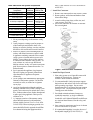
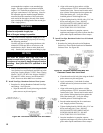
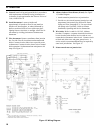
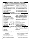
Figure 16: Sequence of Operation
B. Fill boiler with water to normal water line.
C. Prepare to check operation.
1. Obtain gas heating value (in Btu per cubic foot)
from gas supplier.
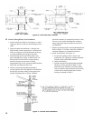
2. Adjust limit. Set cutout pressure (MAIN scale) on
the pressure limit for (1) PSI and differential
pressure (DIFF.) for .5 PSI. These pressures may be
varied to suit individual requirements of the system.
See Figure 25.
3. Connect manometer to gas manifold. Use 1/8 NPT
tapping provided.
4. Temporarilyturnoffallothergas-redappliances.
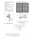
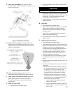
D. Follow Operating Instructions to place boiler in
operation. See Figure 21.
E. Sequence of Operation See Figure 16.
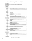
1. If boiler fails to operate properly, see
Troubleshooting Tree on pages 30 and 31.
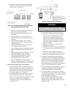
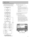
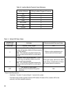
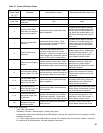
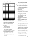
2. Electronic Ignition Modules with LED indicators.
Table 10 cross-references the ignition module
terminal designations to the ignition terminal
numbers in the wiring ladder diagrams. The yellow
LEDindicatesthestatusoftheame,seeTable11.
The green LED indicates the status of the system,
see Table 12. See Figure 17 for LED locations. See
Figure 18 for Troubleshooting Guide.
Figure 17: LED Locations