


26
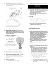
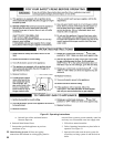
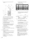
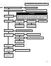
Figure 22: Cleaning Boiler Flue Passages
9. Inspectuepassages.Cleanwithuebrush.See
Figure 22.
10. Inspect heating surface in combustion chamber.
Clean with straight handle wire brush.
12. InstallFlueGasBafes.
13. Install new Gasket (Key No. 2E). Do not reuse
existing material.
14. Install Canopy/Blower Assembly. Tighten Carriage
Bolts to fully compress Gasket.
15. Install Blower Access Panel.
16. Connect Silicone Tubing between Pressure Fitting
on Canopy Assembly and Pressure Switch. Route
through bushings in Blower Access Panel and
Canopy Assembly.
17. Install Jacket Top Panels.
18. Connect vent system. See Figure 7.
19. Connect Blower to Junction Box to Vestibule Wiring
Harness.
F. Main Burners and Firebox
1. Vacuumrebox.Exercisecare-donotdamagebase
insulation.
2. Clean main burners. Brush top of burners with soft
bristle brush. Vacuum to remove any dirt and lint.
3. Vacuum tip of pilot burner.
4. Checkgasoricesforlintanddirt.Cleanas
necessary.
5. Install main burners by reversing procedure to
remove burners.
a. Pilot burner must be installed in original
location. See Table 14.
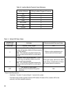
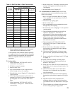
Table 14: Pilot Burner Location
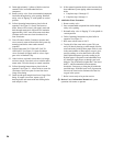
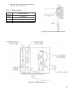
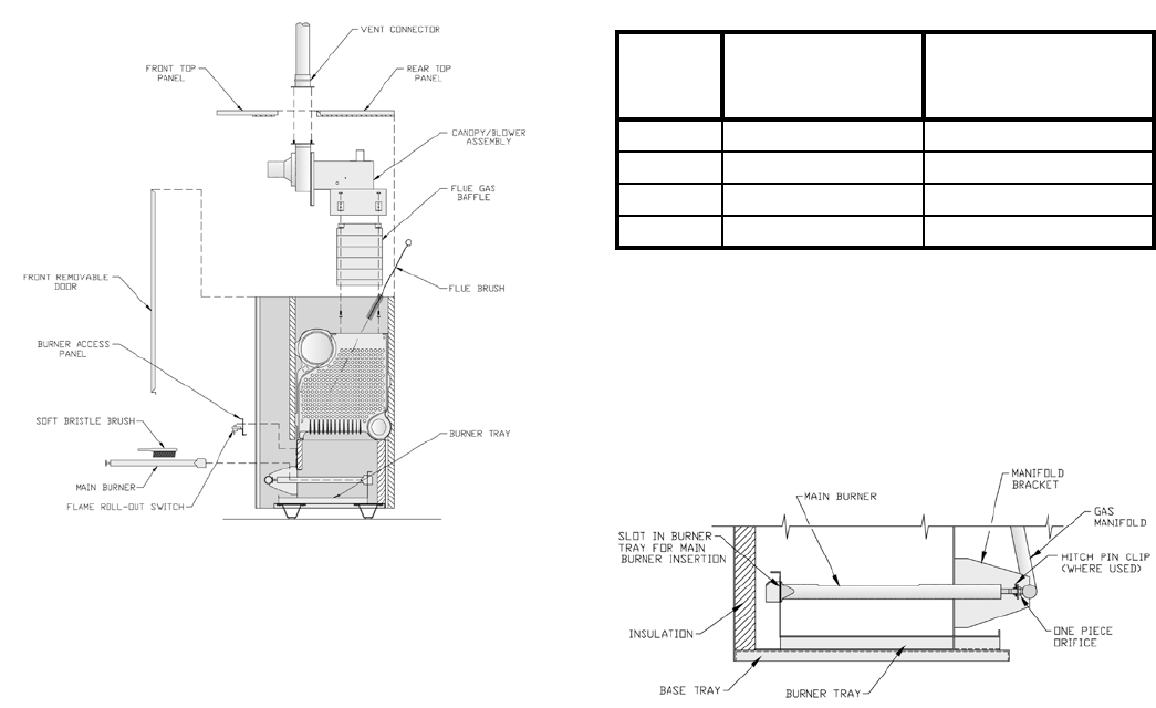
Figure 23: Main Burner Installation
b. Main burners must be properly secured in burner
trayslotatrearofreboxandovergasorice.
See Figure 23.
c. Pilot gas supply, igniter/sensor cable and ground
wire must be reconnected.
d. Burner access panel must be securely in place.
e. Flame rollout switch wires must be reconnected.
G. Check operation. Follow steps B through L from
Section VII: System Start-up.
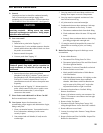
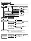
H. Procedure for Measuring Fan Inlet Pressure
(vacuum), See Figure 24.
1. With boiler off, remove hose at pressure switch.
2. With Tee and ¼ inch aluminum stubs, connect water
manometer as shown with additional tubing.
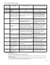
3. Start boiler and read Pressure on Manometer when
boiler water temperature reaches operating
temperature. Refer to Table 15 for minimum
readings.
NOTE: If switch drops-out before boiler reaches
temperature or if pressure readings are below
minimums shown in Table 15, check for cracks in
hose or contact your nearest Burnham
representative.
Boiler
Model
Main Burner with
60° Pilot Bracket *
Pilot Burner Located
Between Main
Burners *
PIN3PV 1 1 & 2
PIN4PV 2 2 & 3
PIN5PV 3 3 & 4
PIN6PV 4 4 & 5
* Main burners numbered left to right as viewed from front
of boiler.