


10
NOTICE
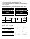
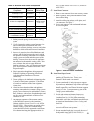
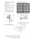
The gasketed vent system components pictured below in Figure A are being phased in and each vent component
is interchangeable with the previously supplied gasket-less venting components. The newer vent components
are generally quicker and easier to join, as they do not require the sealant application and their clamp bands
are attached.
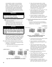
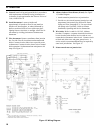
In the event a gasketed vent component and a gasket-
less vent component must be interconnected, follow the
instructions associated with Figure 8B or 8C. The two
guiding principles of these instructions are as follows:
1) Any joining of vent components that involves
at least one gasket-less vent component
always requires the sealant application.
2) The female end of a gasket-less vent
component always requires a clamp band,
regardless of the design of the mating male
vent component.
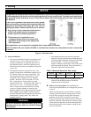
Each gasket-less vent component is supplied with a clamp band and sealant.
A Vent Transition Kit, part number 6116302, is available that contains one clamp band and one 3 ounce tube
of sealant.
Table 7: Maximum Equivalent Vent Length
V. Venting
Figure A: Burnham Vent
A. General Guidelines
1. Vent system installation must be in accordance with
National Fuel Gas Code, NFPA 54/ANSI Z221.3,
Venting of Equipment, or applicable provisions of
localbuildingcodes.Contactlocalbuildingorre
ofcialsaboutrestrictionsandinstallationinspection
in your area.
2. This appliance requires a Special Gas Vent. The
product is designed to use Burnham supplied AL 29-
4C
®
Stainless Steel vent system components. The
following manufacturer's offer similar AL 29-4C
®
components and are approved for use with this
product: Heat-Fab - Saf-T-Vent (800-772-0739);
Flex-L International - Star-34 (800-561-1980);
Protech Systems, Inc. - FasNSeal™ (800-766-3473);
and Z-Flex U. S., Inc. - Z-Vent (800-654-5600).
The use of these alternate manufacturer's venting
systems will require adapters to connect to the
Burnham supplied vent connector and vent terminal.
These adapters are not supplied with this unit and
should be obtained from the supplier of the alternate
manufacturer's venting system. See Table 8 for
complete parts list.
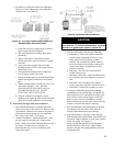
WARNING
Do not use this boiler with galvanized, 304 or 316
stainless steel or any other non AL29-4C
®
based
vent systems.
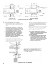
3. Vent length restrictions are based on equivalent
length of vent pipe (total length of straight pipe plus
equivalentlengthofttings).Maximumventlength
is listed in Table 7. Do not exceed maximum
lengths. Minimum vent length is 8 feet. Table 8 lists
equivalentlengthforttings.DonotincludeVent
Terminal in equivalent feet calculation.
4. Do not install venting system components on the
exteriorofthebuildingexceptasspecically
required by these instructions.
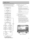
B. Removal of Existing Boiler. For installations not
involving the replacement of an existing boiler, proceed
to Step C.
When an existing boiler is removed from a common
venting system, the common venting system is likely
to be too large for proper venting of the remaining
appliances. At the time of removal of an existing
boiler, the following steps shall be followed with each
appliance remaining connected to the common venting
system placed in operation, while the other appliances
remaining connected to the common venting system
are not in operation:
PIN3PV PIN4PV PIN5PV PIN6PV
45 35 35 35