


21
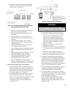
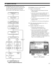
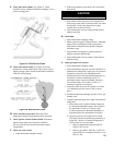
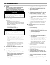
F. Checkpilotburnerame. See Figure 19. Flame
should be steady, medium hard blue enveloping 3/8 to ½
inch of sensing probe.
Figure 19: Pilot Burner Flame
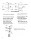
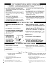
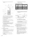
G. Checkmainburnerame. See Figure 20. Flame
shouldhaveclearlydenedinnerconewithnoyellow
tipping. Orange-yellow streaks should not be confused
with true yellow tipping.
H. Check thermostat operation. Raise and lower
temperature setting to start and stop boiler operation.
I. Check ignition control module shutoff. Disconnect
igniter/sensor cable from Terminal 9 (SPARK).
Gas valve should close and pilot and main burners
extinguished.
J. Check low water cutoff.
1. Adjust thermostat to highest setting.
Figure 20: Main Burner Flame
2. With boiler operating, open drain valve and slowly
drain boiler.
CAUTION
Do not drain below gauge glass.
3. Main burners and pilot burner will extinguish and
blower stop when water level drops below low water
cutoff probe. Verify limit, thermostat or other
controls have not shut off boiler.
4. Adjustthermostattolowestsetting.Rellboilerto
normal water line.
K. Check limit.
1. Adjust thermostat to highest setting.
2. Observe pressure gauge. When pressure is indicated,
adjust limit to setting below observed pressure.
Main burners and pilot burner should extinguish,
and blower stop.
3. Adjust limit to setting above observed pressure.
Ignition sequence should begin.
4. Adjust thermostat to lowest setting. Adjust limit to
desired setting.
L. Adjust gas input rate to boiler.
1. Adjust thermostat to highest setting.
2. Check manifold gas pressure. Pressure should be as
printed on the rating label. Adjust gas valve pressure
regulator as necessary (turn adjustment screw
counterclockwise to decrease manifold pressure, or
clockwise to increase manifold pressure). If
speciedpressurecannotbeattained,checkgas
valve inlet pressure. If less than 4.5 inch w.c.,
contact gas supplier for assistance.
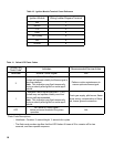
3. Clock gas meter for at least 30 seconds. Use Table
13todeterminegasowrateinCubicFeetper
Hour.
4. DetermineInputRate.Multiplygasowratebygas
heating value.
5. Compare measured input rate to input rate stated on
rating label.
a. Boilermustnotbeoverred.Reduceinputrate
by decreasing manifold pressure. Do not reduce
by more than 0.3 inch w.c. If boiler is still
overred,contactyourBurnhamdistributoror
RegionalOfceforreplacementGasOrice.
b. Increase input rate if less than 98% of rating
label input. Increase manifold gas pressure by as
much as 0.3 inch w.c. If measured input rate is
still less than 98% of rated input:
i. Remove Main Burners per procedure in
Section VIII: Service.
ii. Removegasorices.Drillone(1)drillsize
larger(drillsizeisstampedonorice,orsee
Key No. 4D).