


18
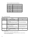
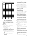
Table 11: Yellow LED Flame Codes
Yellow LED
Flash Code
a
Indicates Recommended Service Action
Heartbeat Normal Flame Signal N/A
2
Weak Flame Signal -
System will operate reliably but ame signal is
less than desired.
Note: This indication may ash temporarily
during or shortly after lightoff on some appli-
cations.
Perform routine maintenance to
assure optimum ame signal.
1
Marginal Flame Signal (less than 1.1 µA) -
System may not operate reliably over time.
Service call recommended.
Note: This indication may ash temporarily
during or shortly after lightoff on some appli-
cations.
Check gas supply, pilot burner, ame
sense wiring, contamination of ame
rod, burner ground connection.
OFF
No Flame or Flame Signal -
below minimum threshold for system
operation.
N/A
a
Flash Code Descriptions
- Heartbeat: Constant ½ second bright, ½ second dim cycles.
- The ash code number signies that the LED ashes X times at 2Hz, remains off for two
seconds, and then repeats sequence.
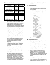
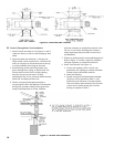
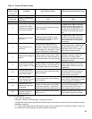
Ignition Module Wiring Ladder Diagram Terminal
MV 1
MV/PV 2
PV 3
GND 4
24V (GND) 5
24V 6
SPARK 9
Table 10: Ignition Module Terminal Cross-Reference