


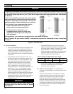

13
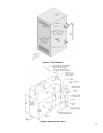
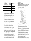
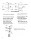
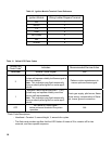
2. Procedure for joining the female end of Burnham
Gasket-Less Vent with the male end of Burnham
Gasketed Vent. See Figure 8C.
Figure 8C: Burnham Gasket-Less Female and
Gasketed Male Vent Joint Detail
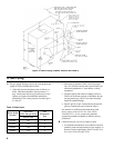
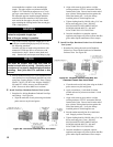
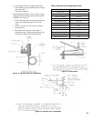
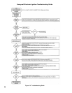
G. Horizontal (Through Wall) Vent Installation.
1. Recommended Installation: Maintain minimum ¼
inch per foot slope in horizontal runs. Slope toward
vent terminal. Position weld seams in vent pipes in
all horizontal runs at the top to avoid condensate
from lying on the seams. See Figure 9.
2. Alternate Installation: Maintain minimum ¼ inch
per foot slope in horizontal runs. Slope toward
boiler. Install a horizontal condensate drain tee after
rstelbow.Positionseamsinventpipesin
horizontal runs at top to avoid condensate from
lying on the seams.
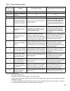
a.Cleanjointsofpipeorttingsusinganalcohol
pad to remove any dirt and grease.
b. Slip a locking band over female (bell) end of
pipe/tting.
c. Apply a continuous ¼ inch bead of sealant
around male end of joint no more than 1/8 inch
from end.
d. Align weld seams in pipes and use a slight
twisting motion to FULLY insert male end into
female end of joint.
e. Smooth sealant around joint for a continuous
seal. Reapply sealant if necessary.
f. Slip the locking band over joint and align closest
bead in locking band with bead in male end of
pipe.
g. Tighten locking band by HAND with a 5/16" nut
driver until snug plus ¼ turn. DO NOT
SECURE JOINTS WITH SHEET METAL
SCREWS OR POP RIVETS. DO NOT
PUNCTURE THE VENT SYSTEM!
h. Once the installation is complete, operate
applianceandinspectalljointstoensurethatue
gases and/or liquid condensate will not escape.
CAUTION
Moisture and ice may form on surfaces around
vent terminal. To prevent deterioration, surfaces
should be in good repair (sealed, painted etc.)
3. Vent terminal location restricted per following:
a. Minimum 12 inches above grade or normally
expected snow accumulation level, or 7 feet
above grade if located adjacent to public
walkway. Do not install over public walkway
where local experience indicates condensate or
vapor from Category III appliances creates a
nuisance or hazard .
b. Minimum 3 feet above any forced air inlet
located within 10 feet.
c. Minimum 4 feet below, 4 feet horizontally from,
or 1 foot above any door, window, or gravity air
inlet.
d. Minimum 4 feet horizontally from electric
meters, gas meters, regulators, and relief valves.
e. Minimum 12 inches from overhang or corner.
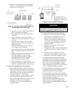
4. Use single wall thimble when passing through
combustible outside wall (thimble use optional for
noncombustible wall). Insert thimble through wall
fromoutside.Secureoutsideangetowallwith
nails or screws, and seal with adhesive material.
Installinsideangetoinsidewall,securewithnails
or screws, and seal with adhesive material.
5. For noncombustible wall when thimble is not used,
size opening such that female (bell) end with
locking band attached cannot pass through.
6. Join vent terminal to vent pipe. Locate vent pipe
suchthatbell/lockingbandisushwithoutsidewall
(oroutsideangeofthimble,ifused)whenjoinedto
inside vent piping. See Figure 10.
7. Insert vent pipe through thimble/opening from
outside and join to vent system. Apply sealant
between vent pipe and opening/thimble to provide
weathertight seal.
Figure 9: Horizontal Vent Installation