


82
III. Component Test Procedures
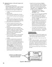
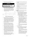
A. Flame Signal Check
1. The ame signal can be checked between terminal
number 7 on the low voltage terminal strip and
ground. A good signal reading should be 6 VDC or
greater.
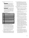
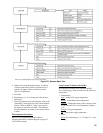
Hotwater - Indirect water heater thermostat (“1” =
Calling, “0” = Not Calling)
Pump - Heating circulator (“1” = On, “0” = Off)
Air-switch - Status of air pressure switch (“1” =
Closed, “0” = Open)
Gaspressure - This is actually the status of the high
limit (“1” = Closed, “0” = Open)
GasValve - Status of gas valve (“1” = Open , “0” =
Closed)
Flame - Shows whether the MCBA detects the
presence of the burner ame (“1” = Flame, “0” = No
Flame)
DHW Pump - Indirect water heater circulator (“1” =
On, “0” = Off)
3. RPM:
Fan - Actual speed of fan
Set - Target speed of fan.
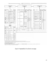
Reading the MCBA Error Log
1. The MCBA keeps a log of the last six error codes.
To view these error codes select “Read from
MCBA” from the Error Menu.
2. This data can be saved as a le to disk by selecting
“Save to le” from the Error Menu or printed by
selecting “Print” from the same menu.
3. Error codes can also be removed from the memory
of the MCBA by selecting “Clear in MCBA” from
the Error Menu.
2. If the signal is lower then 6 VDC, check the
continuity of the ground wire between the ignitor
and the junction box. If the ground wire is suspect
replace the ground wire.
3.
If the ground wire is in good condition, remove
the ignitor and ame sensor to inspect the ceramic
insulator for cracks. If none are found, sand off
any oxide deposits which formed on the electrodes.
If the insulator is cracked or the electrode cannot
be properly cleaned, replace the ignitor and ame
sensor. When replacing the ignitor and ame sensor,
be sure to replace the ignitor and ame sensor
gasket as well.
4.
Other problems that can cause a low ame signal
include:
• An improperly adjusted throttle (conrm that the
CO
2
is within the limits shown in the installation
manual).
• Fouling of the burner (remove the burner and
clean with compressed air).
• Low inlet gas pressure (verify that gas pressure
is within the limits shown on the rating plate).
• Grounded 24 VAC or sensor wiring (this problem
will result in no ame voltage reading, but will
normally not result in an E02 error because there
is still adequate ame current).
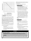
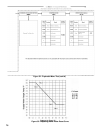
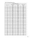
B. NTC Temperature Sensors
1. The supply, return, ue, and outdoor reset sensors
used on the Alpine are of the resistance type.
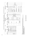
2. The Table 27 shows the range of resistance values
for these sensors at various temperatures.