


13
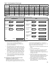
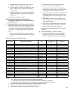
Boiler
Model
3” Combustion Air Pipe
(Equivalent Length)
4” Combustion Air Pipe
(Equivalent Length)
3” Vent Pipe
(Equivalent Length)
4” Vent Pipe
(Equivalent Length)
Min. Max. Min. Max. Min. Max. Min. Max.
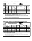
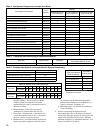
ALP080 21-7/8 In. 60 Ft. --- --- 21-7/8 In. 60 Ft. --- ---
ALP105 21-7/8 In. 60 Ft. --- --- 21-7/8 In. 60 Ft. --- ---
ALP150 --- --- 21-7/8 In. 60 Ft. 21-7/8 In. 60 Ft. --- ---
ALP210 --- --- 21-7/8 In. 60 Ft. 21-7/8 In. 60 Ft. --- ---
ALP285 --- --- 32 In. 60 Ft. --- --- 32 In. 60 Ft.
ALP399 --- --- 32 In. 60 Ft. --- --- 32 In. 60 Ft.
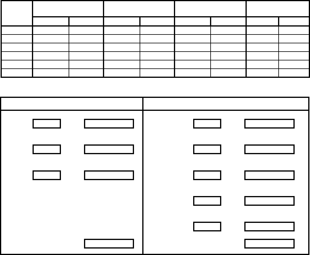
Table 7: Vent/Combustion Air Pipe Length
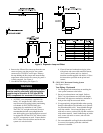
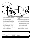
Combustion Air Vent
90° elbow(s) PVC Supplied 30” straight CPVC
Quantity = x 5’ = equiv. ft. a. Length ft. = 2.5 x 1 = 2.5 equiv. ft. a.
45° elbow(s) PVC Supplied 90° elbow CPVC
Quantity = x 2.5’ = equiv. ft. b. Quantity = 1 x 5’ = 5 equiv. ft. b.
Straight pipe PVC 90° elbow(s) PVC
Length ft. = x 1 = equiv. ft. c. Quantity = x 5’ = equiv. ft. c.
45° elbow(s) PVC
Quantity = x 2.5’ = equiv. ft. d.
Straight pipe PVC
Length ft. = x 1 = equiv. ft. e.
Total* a.+b.+c. = equiv. ft. Total* a.+b.+c.+d.+e.= equiv. ft.
* Total cannot exceed 60 equiv. ft. length.
Vent and combustion air terminals do not count towards total equiv. ft.
Combustion Air/Vent, Equivalent Length Work Sheet
This sheet is supplied to assist in vent/combustion air, equivalent length calculating
Note: For one or two family dwellings, re
resistance rating requirement may not need to be
met, but is recommended.
7. Plan venting system to avoid possible contact with
plumbing or electrical wires. Start at vent connector
at rear of boiler and work towards vent termination.
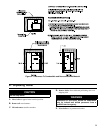
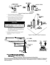
8. Design the Vent System to allow a 3/8” of thermal
expansion per 10 feet of CPVC/PVC pipe. Runs of
20 ft. or longer that are restrained at both ends must
use an offset or expansion loop. Refer to Figure 3.
9. Follow all manufacturer instructions and warnings
when preparing pipe ends for joining and using the
primer and the cement.
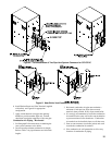
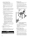
D. Installation of Two-Pipe CPVC/PVC Gas Vent/
Combustion Air System Connector
The boiler two pipe vent system connector for CPVC/
PVC and gasket are shipped inside the vent carton. The
vent connector mounting hardware - six (6) #8 x ½”
black oxide round head Phillips sheet metal screws - are
shipped inside Miscellaneous Part Carton.
1. Remove the vent connector and gasket from the vent
carton.
2. Locate six mounting screws.
3. Position the vent connector and gasket onto jacket
combination rear/bottom panel and insert vent
connector inner stainless steel vent pipe into the heat
exchanger vent outlet.
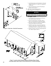
4. Align vent connector plate and gasket clearance
holes with rear/bottom panel engagement holes; then
secure the collar and gasket to rear/bottom panel
with six mounting screws. See Figure 4.
5. Flue temperature sensor, factory attached to the
boiler wiring harness, is secured to the boiler rear/
bottom panel with tape.