


25
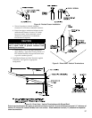
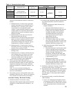
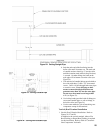
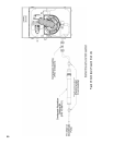
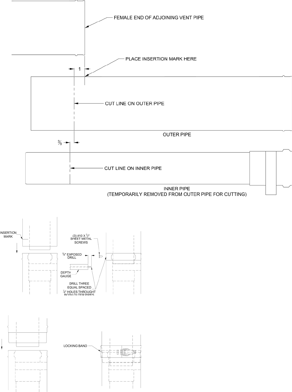
Figure 22: Cutting Straight Pipe
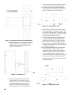
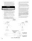
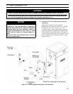
Figure 23: Joining Cuttable Pipe
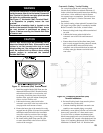
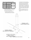
Figure 24: Joining Non-Cuttable Pipe
b. Push the male end of the rst tting into the
boiler collar until it bottoms out. The male end
of cuttable sections should go 1” into the collar
until the insertion mark (made in Step 2d above)
is covered. On other ttings, the bead on the
male pipe will be bottom out on the collar (see
Figure 24).
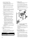
c.
The male end of cuttable ttings must be held to
the collar with three (3) #10 x 1/2” sheet metal
screws. Drill a 1/8 hole through both outer pipes
to start this screw. Use a drill stop or other
means to ensure that the drill bit does not
penetrate more than 3/8” into the outer pipe.
Do not use a sheet metal screw longer than
1/2” (see Figure 23).
d. Use locking bands (provided with all ttings) to
secure non-cuttable pipe, as well as ttings, to
the boiler collar (see Figure 24).
e. Use the same method to join all remaining vent
components except for the terminal.
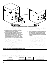
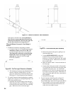
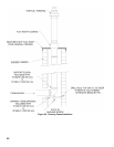
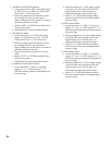
Vertical (Roof Terminal Installation
1. Vertical (Roof) Terminal Installation. Refer to
Figures 26, 27 and 28.
In addition to the vertical terminal, either a Flat
Roof Flashing or Sloped Roof Flashing is required
for this installation. Refer to Table 8 ‘Concentric
Vent Components’ for details.