


50
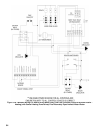
• Black – Line voltage “hot”
• White – “Neutral” for boiler and circulators
• Red – “Heating” circulator “hot”
• Blue – “Indirect Water Heater “ circulator “hot”
• Green – Ground connection
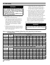
2. Maximum circulator continuous current draw is 2A.
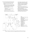
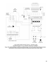
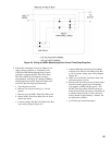
With primary/secondary piping, it may be desirable
to use the boiler to directly control the primary
circulator in addition to the secondary circulator. If
this is done, control both heating circulators using
a relay with a 120VAC coil, such as a Honeywell
R4222, as shown in Figures 37A and 37B. Select a
relay with a contact rating in excess of the combined
draw of the two circulators.
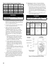
3. Low Voltage Connections (Figure 35) – These
connections are screw terminals located on the
terminal strip next to the junction box on the left:
• Terminals 1 and 8 – “Heating” thermostat
connections
• Terminals 5 and 6 – “External Limit Control”
connections
• Terminals 3 and 4 – “Outdoor Reset Sensor”
connections
• Terminals 2 and 4 – “Domestic Indirect Water
Heater” thermostat connections
• Terminal 7 – “Flame Signal Reading”
• Heat anticipator setting for the thermostat
connection is 0.1 A when thermostat is connected
directly to terminals 1 and 8.
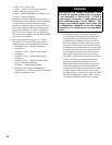
WARNING
When making low voltage connections, make
sure that no external power source is present
in the thermostat or limit circuits. If such a
power source is present, it could destroy the
boiler’s Microprocessor Control (MCBA). One
example of an external power source that could
be inadvertently connected to the low voltage
connections is a transformer in old thermostat
wiring.
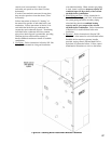
4. If the outdoor sensor is connected to terminals 3
and 4, the boiler will adjust the target space heating
set point supply water temperature downwards
as the outdoor air temperature increases. If used,
this sensor should be located on the outside of the
structure in an area where it will sense the average
air temperature around the house. Avoid placing this
sensor in areas where it may be covered with ice or
snow. In general, locations where the sensor will
pick up direct radiation from the sun should also
be avoided. Avoid placing the sensor near potential
sources of electrical noise such as transformers,
power lines, and uorescent lighting. Wire the
sensor to the boiler using 22 gauge or larger wire.
As with the sensor, the sensor wiring should be
routed away from sources of electrical noise. Where
it is impossible to avoid such noise sources, wire
the sensor using a 2 conductor, UL Type CM, AWM
Style 2092, 300Volt 60°C shielded cable. Connect
one end of the shielding on this cable to ground.