


71
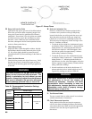
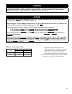
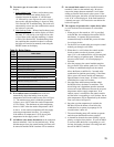
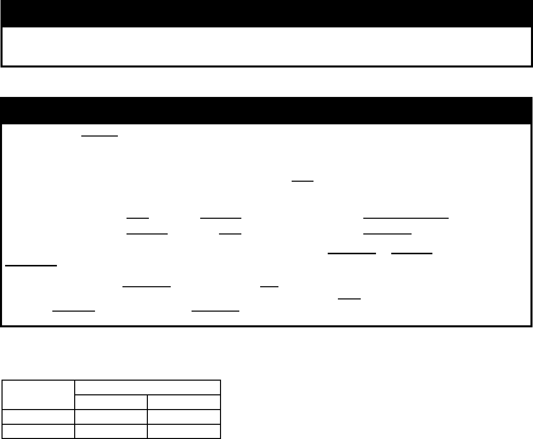
Fuel
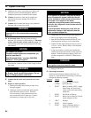
Inlet Pressure (Inches w.c.)
Min. Max.
Natural Gas 4.0 14.0
LP 11.0 14.0
Table 24: Inlet Pressure Limits
• Apply the “Boiler Conversion Label” to a
conspicuous surface on, or adjacent to, the outer
boiler jacket. Fill in the date of the conversion
and the name and address of the company
making the conversion with a permanent marker.
1
1. Refer to Section XI “System Start-up” of this manual
and perform any checks not already completed.
WARNING
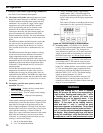
The throttle adjustments shown in Table 22 are approximate. The nal throttle setting must be found using
a combustion analyzer. Leaving the boiler in operation with a CO level in excess of the value shown in
Table 23 could result in injury or death from carbon monoxide poisoning.
NOTICE
If the throttle is very far out of adjustment on the “rich” (counter-clockwise) side, the boiler burner may be
running at 0% Excess Air or even with air deciency.
At 0% Excess Air the CO
2
readings will be either 11.9% CO
2
for Natural Gas or 13.8% CO
2
for LP Gas (O
2
will
be 0%) and CO level will be extremely high (well over 1000 PPM).
If the burner operates with air deciency, the following phenomena may be observed:
% CO
2
will actually drop (% O
2
will increase) as the throttle is turned counterclockwise
% CO
2
will actually increase (% O
2
will drop) as the throttle is turned clockwise
If the boiler appears to operate with air deciency, turn the throttle clockwise to increase the amount of
Excess Air to the burner.
As the throttle is turned clockwise, the CO
2
level will rise, eventually peaking @ 11.8% or 13.8%, depending
of the type of gas being used, before falling (conversely, O
2
level will drop to 0% before rising). After this
happens, continue turning the throttle clockwise, until CO
2
level drops (or O
2
level increases) to the values
shown in Table 20 or Table 23.