


48
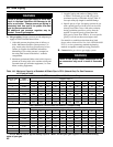
C. Pressure test. See Table 17 for Alpine Min./Max.
Pressure Ratings. The boiler and its gas connection
must be leak tested before placing boiler in operation.
1. Protect boiler gas control valve. For all testing over
½ psig, boiler and its individual shutoff valve must
be disconnected from gas supply piping. For testing
at ½ psig or less, isolate boiler from gas supply
piping by closing boiler’s individual manual shutoff
valve.
2. Locate leaks using approved combustible gas non-
corrosive leak detector solution.
DANGER
Do not use matches, candles, open ames or
other ignition source to check for leaks.
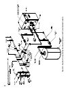
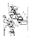
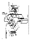
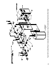
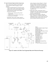
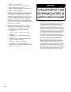
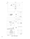
Figure 34: Recommended Gas Piping
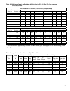
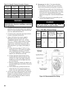
Table 16: Specic Gravity Correction Factors
Boiler
Model
No.
Natural/LP
Gas
Max.
Pressure
(in. w.c.)
Natural Gas
Min. Pressure
Inlet to Gas Valve
(in. w.c.)
LP Gas
Min. Pressure
Inlet to Gas
Valve
(in. w.c.)
ALP080
14 4.0 11.0
ALP105
ALP150
ALP210
ALP285
ALP399
Table 17: Min./Max. Pressure Ratings
Specic
Gravity
Correction
Factor
Specic
Gravity
Correction
Factor
0.60 1.00 0.90 0.82
0.65 0.96 1.00 0.78
0.70 0.93 1.10 0.74
0.75 0.90 1.20 0.71
0.80 0.87 1.30 0.68
0.85 0.81 1.40 0.66
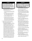
WARNING
Gas supply to boiler and system must be
absolutely shut off prior to installing or servicing
boiler gas piping.
1. Use methods and materials in accordance with local
plumbing codes and requirements of gas supplier. In
absence of such requirements, follow National Fuel
Gas Code, NFPA 54/ANSI Z223.1.
2.
Use thread (joint) compounds (pipe dope) resistant
to action of liqueed petroleum gas.
3. Alpine (ALP) boilers have factory supplied
Miscellaneous Part Carton (P/N 101777-01
- ALP080 thru ALP210; 101777-02 - ALP285;
101777-03 - ALP399), which includes gas piping
components to connect boiler gas valve to gas
supply system. Install these components prior to
connecting boiler to gas supply system piping as
follows:
a. Locate and remove either ½” NPT x 6” long
black nipple and ½” NPT external gas shutoff
valve (ALP080 thru ALP210), or ¾” NPT x
6” long black nipple and ¾” NPT external gas
shutoff valve (ALP285 thru ALP399).
b. Feed the appropriate nipple through factory
installed jacket left side panel grommet (refer
to Figure 1A or 1B for gas supply connection
identication) and screw the nipple into boiler
gas valve inlet port.
c. Mount the appropriate external gas shutoff valve
onto the threaded nipple end outside of the jacket
left side panel.
d. Install sediment trap, ground-joint union and
manual shut-off valve upstream of boiler gas
control valve and outside jacket. See Figure 34.
4. All above ground gas piping upstream from manual
shut-off valve must be electrically continuous and
bonded to a grounding electrode. Do not use gas
piping as grounding electrode. Refer to National
Electrical Code, NFPA 70.