


44
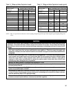
NOTICE
Where it is not possible to install a separate
boiler loop, the system circulator must be
sized to ensure that the ow through boiler
stays within the dened parameters to prevent
overheating when the boiler is red at it’s full
rated input. Install a ow meter to measure the
ow, or re the boiler at full rate and ensure the
boiler DT does not exceed 35°F.
2. Direct connection of Alpine (ALP) boiler to
heating system, similar to a conventional boiler, is
NOT RECOMMENDED because:
a.
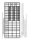
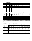
The ow rate through system must be the same
as through boiler and fall within limits specied
in Table 11.
b.
Pressure drop through entire system must be
known, added to pressure drop through boiler,
and, a circulator selected to provide required
ow at total calculated pressure drop.
c. It is often very difcult to accurately calculate
the pressure drop through the system.
d. In replacement installations, it may be nearly
impossible to get an accurate measurement of
piping amount and number of ttings in the
system. If system is zoned, the system ow rate
may drop well below recommended minimum
ow when only a single zone is calling for heat.
C. Piping Standard Installation Requirements.
Observe the following guidelines when making the
actual installation of the boiler piping:
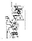
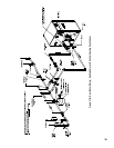
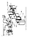
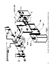
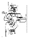
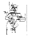
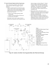
1. Pressure Relief Valve (Required) - The relief valve
is packaged loose with boiler and must be installed
in the location shown in Figure 30 “Factory
Supplied Piping and Trim Installation”. The relief
valve must be installed with spindle in vertical
position. Installation of the relief valve must comply
with ASME Boiler and Pressure Vessel Code,
Section IV. The standard factory shipped relief valve
is rated for 30 PSI maximum working pressure.
Optional 50 PSI maximum working pressure
rated relief valve is available. If the valve is to be
replaced, the replacement valve must have a relief
capacity equal or exceeding the boiler DOE Heating
Capacity (models ALP080 thru ALP285) or the
boiler I=B=R Gross Output rating (model ALP399).
Pipe the relief valve discharge to a location where
hot water or steam will not create hazard or property
damage if the valve opens. The end of the discharge
pipe must terminate in an unthreaded pipe. If the
relief valve is not piped to a drain, it must terminate
at least 6” above the oor. Do not run relief valve
discharge piping through an area prone to freezing.
The termination of discharge piping must be in an
area where it will not become plugged by debris.
WARNING
Pressure relief valve discharge piping must be
piped such that the potential of severe burns
is eliminated. DO NOT pipe in any area where
freezing could occur. DO NOT install any shut-off
valves, plugs or caps. Consult Local Codes for
proper discharge piping arrangement.
2. Circulator (Required) – Usually at least two
circulators will be required to properly install a
Alpine™ Series boiler. See Section B above for
information on sizing the circulators.
3.
Expansion Tank (Required) - If this boiler is
replacing an existing boiler with no other changes
in the system, the old expansion tank can generally
be reused. If the expansion tank must be replaced,
consult the expansion tank manufacturer’s literature
for proper sizing.
4. Fill Valve (Required) – Either manual
(recommended) or automatic ll valve may be used.
However, if automatic rell is employed, a water
meter must be added to evaluate the makeup water
volume taken after initial ll and eliminate any
water leakage as early as possible.
5. Automatic Air Vent (Required) -At least one
automatic air vent is required. Manual vents will
usually be required in other parts of the system to
remove air during initial ll.
6. Manual Reset High Limit (Required by some
Codes) - This control is required by ASME CSD-1
and some other codes. Install the high limit in the
boiler supply piping just above the boiler with no
intervening valves. Set the manual reset high limit
to 200°F. Wire the limit per Figures 36, 37A and
37B in VIII Electrical Section.
7. Flow Control Valve (Strongly Recommended)
- The ow control valve prevents ow through the
system unless the circulator is operating. Flow
control valves are used to prevent gravity circulation
or “ghost ows” in circulator zone systems through
zones that are not calling for heat.
8. Isolation Valves (Strongly recommended) -
Isolation valves are useful when the boiler must be
drained, as they will eliminate having to drain and
rell the entire system.
9. Drain Valve (Required) – Drain valve is packaged
loose with boiler and must be installed in the
location shown in Figure 30 “Factory Supplied
Piping and Trim Installation”.
10. Low Water Cutoff (Required by some Codes)
– LWCO with harness and LWCO transformer are
available as optional components. Order Complete
Kit (Part No. 102097-01) when required.