


66
A. Verify that the venting, water piping, gas piping and
electrical system are installed properly. Refer to
installation instructions contained in this manual.
B. Conrm all electrical, water and gas supplies are
turned off at the source and that vent is clear of
obstructions.
C. Conrm that all manual shut-off gas valves between
the boiler and gas source are closed.
WARNING
Completely read, understand and follow all
instructions in this manual before attempting
start up.
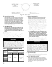
D. If not already done, ush the system to remove
sediment, ux and traces of boiler additives. This must
be done with the boiler isolated from the system. Fill
entire heating system with water meeting the following
requirements:
NOTICE
pH between 8.2 and 9.5.
If system contains aluminum components, pH
must be less than 8.5
Total Dissolved Solids - less than 2500 PPM
Hardness - 3 to 9 grains/gallon.
Pressurize the system to at least 12 PSI. Purge air from
the system.
WARNING
The maximum operating pressure of this boiler
is 30 psig. Never exceed this pressure. Do not
plug or change pressure relief valve.
E. Conrm that the boiler and system have no water
leaks.
F. Prepare to check operation.
1. Obtain gas heating value (in Btu per cubic foot)
from gas supplier.
2. Alpine gas valves have inlet and outlet pressure
taps with built-in shut off screw. Turn each
screw from fully closed position three to four
turns counterclockwise to open taps. Connect
manometers to pressure taps on gas valve.
XI. System Start-up
NOTICE
If it is required to perform a long term pressure
test of the hydronic system, the boiler should
rst be isolated to avoid a pressure loss due to
the escape of air trapped in the boiler.
To perform a long term pressure test including
the boiler, ALL trapped air must rst be removed
from the boiler.
A loss of pressure during such a test, with no
visible water leakage, is an indication that the
boiler contained trapped air.
3.
Temporarily turn off all other gas-red appliances.
4. Turn on gas supply to the boiler gas piping.
5. Open the eld installed manual gas shut-off valve
located upstream of the gas valve on the boiler.
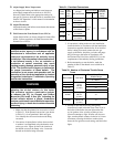
6.
Conrm that the supply pressure to the gas valve is
14 in. w.c. or less. Refer to Table 21 for minimum
supply pressure.
7. Using soap solution, or similar non-combustible
solution, electronic leak detector or other approved
method. Check that boiler gas piping valves, and
all other components are leak free. Eliminate any
leaks.
DANGER
Do not use matches, candles, open ames or
other ignition source to check for leaks.
8. Purge gas line of air.
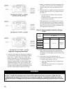
G. Operating Instructions
Start the boiler using the lighting instructions, see
Figure 46. After the boiler is powered up, it should go
through the following sequence.
Sequence Display Meaning
1 U.125 Checking internal software
or Blank (power-up only)
2 0.SWT Boiler in standby. SWT = Supply
Water Temp. No call for heat.
(After call for heat from heating
thermostat)
3 A.SWT Self-Check on Start-up
4 5.SWT Blower and circulator on. Check-
ing for adequate air ow.
5 1.SWT Prepurge
6 2.SWT Trial for ignition
7 3.SWT Flame established. Boiler re-
sponding to a call for heat.