


46
VII. Gas Piping
WARNING
Failure to properly pipe gas supply to boiler may
result in improper operation and damage to the
boiler or structure. Always assure gas piping is
absolutely leak free and of the proper size and
type for the connected load.
An additional gas pressure regulator may be
needed. Consult gas supplier.
A. Size gas piping. Design system to provide adequate gas
supply to boiler. Consider these factors:
1. Allowable pressure drop from point of delivery to
boiler. Maximum allowable system pressure is ½
psig. Actual point of delivery pressure may be less;
contact gas supplier for additional information.
Minimum gas valve inlet pressure is stamped on
the rating label located in the boiler’s vestibule
compartment.
2. Maximum gas demand. Refer to the boiler’s input as
printed on its rating label. Also consider existing and
expected future gas utilization equipment (i.e. water
heater, cooking equipment).
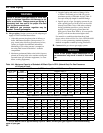
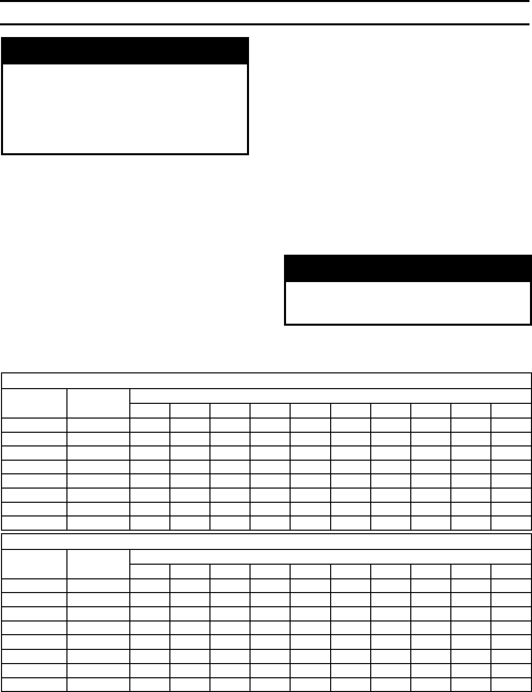
Inlet Pressure 0.5 PSI or less; 0.3 Inch W.C. Pressure Drop
Nominal Pipe
Size, In.
Inside
Diameter, In.
Length of Pipe, Ft.
10 20 30 40 50 60 70 80 90 100
½ 0.622 131 90 72 62 55 50 46 42 40 38
¾ 0.824 273 188 151 129 114 104 95 89 83 79
1 1.049 514 353 284 243 215 195 179 167 157 148
1¼ 1.380 1056 726 583 499 442 400 368 343 322 304
1½ 1.610 1582 1087 873 747 662 600 552 514 482 455
2 2.067 3046 2094 1681 1439 1275 1156 1063 989 928 877
2½ 2.469 4856 3337 2680 2294 2033 1842 1695 1576 1479 1397
3 3.068 8584 5900 4738 4055 3594 3256 2996 2787 2615 2470
Table 14A: Maximum Capacity of Schedule 40 Black Pipe in CFH* (Natural Gas) For Gas Pressures
of 0.5 psig or Less
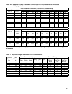
Inlet Pressure 0.5 PSI or less; 0.5 Inch W.C. Pressure Drop
Nominal Pipe
Size, In.
Inside
Diameter, In.
Length of Pipe, Ft.
10 20 30 40 50 60 70 80 90 100
½ 0.622 172 118 95 81 72 65 60 56 52 50
¾ 0.824 360 247 199 170 151 137 126 117 110 104
1 1.049 678 466 374 320 284 257 237 220 207 195
1¼ 1.380 1392 957 768 657 583 528 486 452 424 400
1½ 1.610 2085 1433 1151 985 873 791 728 677 635 600
2 2.067 4016 2760 2217 1897 1681 1523 1402 1304 1223 1156
2½ 2.469 6401 4400 3533 3024 2680 2428 2234 2078 1950 1842
3 3.068 11316 7778 6246 5345 4738 4293 3949 3674 3447 3256
* 1 CFH of Natural Gas is approximately equal to 1 MBH; contact your gas supplier for the actual heating
value of your gas.
3. Length of piping and number of ttings. Refer
to Tables 14A (natural gas) or 14B (LP gas) for
maximum capacity of Schedule 40 pipe. Table 15
lists equivalent pipe length for standard ttings.
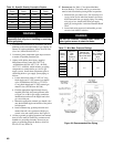
4.
Specic gravity of gas. Gas piping systems for gas
with a specic gravity of 0.60 or less can be sized
directly from Tables 14A or 14B, unless authority
having jurisdiction species a gravity factor be
applied. For specic gravity greater than 0.60,
apply gravity factor from Table 16. If exact specic
gravity is not shown choose next higher value.
For materials or conditions other than those listed
above, refer to National Fuel Gas Code, NFPA54/ANSI
Z223.1, or size system using standard engineering
methods acceptable to authority having jurisdiction.
B. Connect boiler gas valve to gas supply system.
WARNING
Failure to use proper thread compounds on all
gas connectors may result in leaks of ammable
gas.