


12
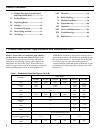
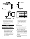
Vent Pipe Pipe Direction Enclosure
Minimum Clearance To
Combustible Material, Inches
CPVC/PVC Venting Vertical or Horizontal Enclosed at all Sides 1” Vent/0” Combustion Air
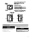
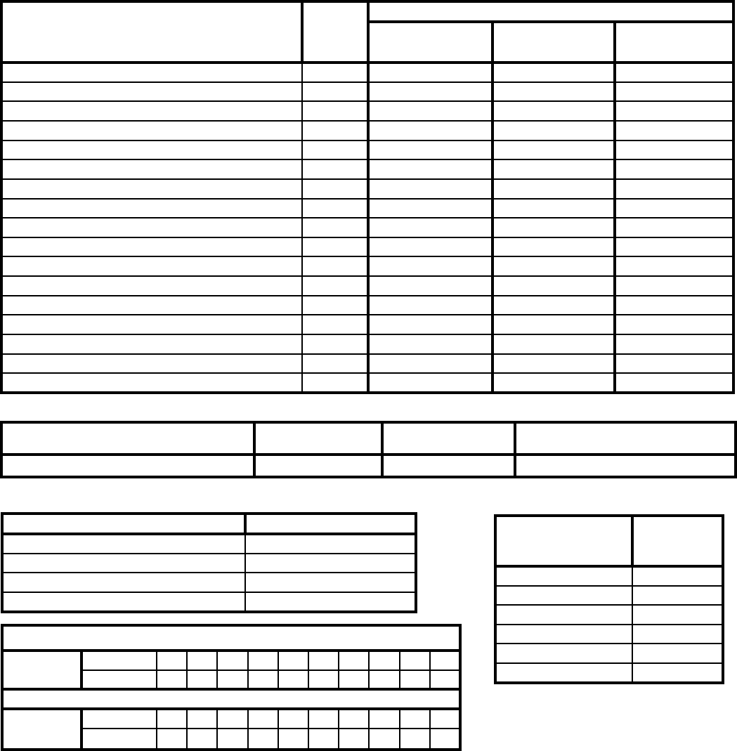
Table 5: Clearances from Vent Piping to Combustible Material
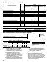
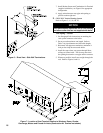
Vent System Components
Part
Number
Quantity
ALP080 & ALP105
(P/N 102189-01)
ALP150 & ALP210
(P/N 102189-02)
ALP285 & ALP399
(P/N 102189-03)
3” Schedule 40 PVC Tee Combustion Air/Vent Terminal 102190-01 2 1 ---
4” Schedule 40 PVC Tee Combustion Air/Vent Terminal 102190-02 --- 1 2
3” Stainless Steel Rodent Screens 102191-01 2 1 ---
4” Stainless Steel Rodent Screens 102191-02 --- 1 2
3” x 30” Schedule 40 CPVC Pipe 102193-01 1 1 ---
4” x 30” Schedule 40 CPVC Pipe 102193-02 --- --- 1
3” Schedule 80 CPVC 90° Elbow 102192-01 1 1 ---
4” Schedule 80 CPVC 90° Elbow 102192-02 --- --- 1
8 oz. Bottle of Transition Cement 102195-01 1 1 1
8 oz. Bottle of Primer 102194-01 1 1 1
Burnham Vent Supplement Manual 102188-01 1 1 1
Two Pipe Vent System Connector for CPVC/PVC 102183-01 1 --- ---
Two Pipe Vent System Connector for CPVC/PVC 102183-02 --- 1 ---
Two Pipe Vent System Connector for CPVC/PVC 102183-03 --- --- 1
Two Pipe Vent System Connector for CPVC/PVC Gasket 102185-01 1 1 ---
Two Pipe Vent System Connector for CPVC/PVC Gasket 102185-02 --- --- 1
Silicone Vent Sensor Cap 102153-01 1 1 1
Table 4: Vent System Components Included with Boiler
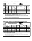
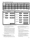
Table 6: Burnham Vent System and Combustion Air System Components
Vent System Component Equivalent Length (Ft.)
3” Schedule 40 CPVC Pipe x 30 Inches 2.5
4” Schedule 40 CPVC Pipe x 30 Inches 2.5
3” Schedule 80 CPVC 90° Elbow 5
4” Schedule 80 CPVC 90° Elbow 5
Combustion Air
System Component
(Parts by Others)
Equivalent
Feet of Pipe*
3” or 4” ID Pipe x 1 Ft. 1
3” or 4” ID Pipe x 2 Ft. 2
3” or 4” ID Pipe x 4 Ft. 4
3” or 4” ID Pipe x 5 Ft. 5
3” or 4” 90° Elbow 5
3” or 4” 45° Elbow 5
*Equivalent Feet of Pipe Based on
Standard 4” PVC Design
Maximum Number of 90’s and Straight Pipe
Vent Pipe
# of 90’s 1 2 3 4 5 6 7 8 9 10
Feet of Pipe 55 50 45 40 35 30 25 20 15 10
Combustion
Air Pipe
# of 90’s 1 2 3 4 5 6 7 8 9 10
Feet of Pipe 55 50 45 40 35 30 25 20 15 10
to public walkway. Do not install over public
walkway where local experience indicates
appliance ue gas vapor or condensate creates a
nuisance or hazard.
b. Minimum three (3) feet above any forced
combustion air located within ten (10) feet.
c. Direct Vent - Minimum one (1) foot below, one
(1) foot horizontally from, or one (1) foot above
any door, window, or gravity air inlet.
d. Minimum four (4) feet horizontally from electric
meters, gas meters, regulators, and relief valves.
This distance may be reduced if equipment is
protected from damage due to condensation or
vapor by enclosure, overhangs, etc.
e. Minimum twelve (12) inches from overhang or
corner of building.
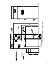
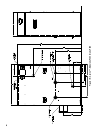
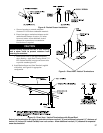
6. Enclose vent passing through occupied or
unoccupied spaces above the boiler with material
having a re resistance rating of at least equal to the
rating of the adjoining oor or ceiling. Maintain
minimum clearances to combustible materials. See
Figure 2 and Table 5 for details.