


56
IX. Boiler Stacking
For installations with unusually high space heating
and/or domestic hot water heating loads, where employing
two (2) Alpine (ALP) boilers will offer the benets of
greater operational efciency, oor space savings and boiler
redundancy, the Alpine (ALP) boilers may be installed
stacked one on the top of the other. Refer to Table 18
“Alpine (ALP) Boiler Model Stacking Combinations” for
details.
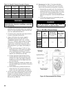
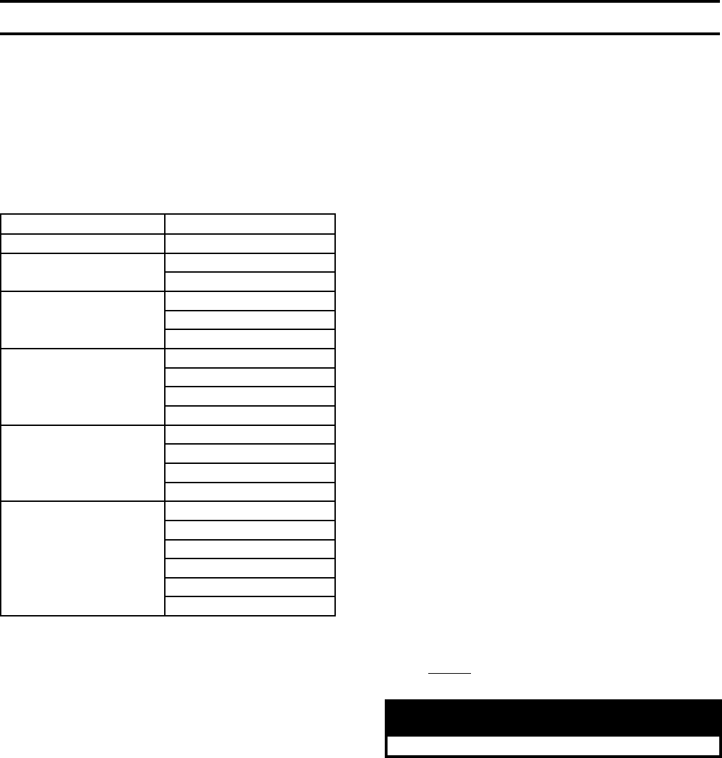
Table 18: Alpine (ALP) Boiler Model
Stacking Combinations
Bottom Boiler Model Top Boiler Model
ALP080 ALP080
ALP105
ALP080
ALP105
ALP150
ALP080
ALP105
ALP150
ALP210
ALP080
ALP105
ALP150
ALP210
ALP285
ALP080
ALP105
ALP150
ALP285
ALP399
ALP080
ALP105
ALP150
ALP210
ALP285
ALP399
A. To eld assemble individual Alpine (ALP) boilers
into a stackable conguration, use the steps below:
1. Position the bottom boiler rst. Refer to Sections II
“Pre-Installation” and III “Unpacking Boiler” of the
manual for details. Always position higher input
boiler model as bottom boiler.
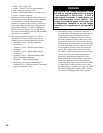
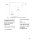
2. Each Alpine (ALP) boiler is factory packaged with
two (2) Stacking Boiler Attachment Brackets (P/N
101679-01) and the bracket mounting hardware [six
(6) self-drilling hex washer head plated #8 x ½”
long screws, P/N 80860743]. Locate and remove
the brackets and the hardware. The Stacking Boiler
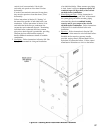
Attachments Bracket has three 7/32” diameter holes
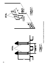
punched in a triangular pattern. See Figure 39
“Stacking Boiler Attachment Bracket Placement”.
3. Alpine (ALP) boiler left and right side panels have
a series of dimples at panel top and bottom. These
dimples are positioning dimples for Stacking Boiler
Attachment Bracket mounting screws. Side panel
bottom positioning dimples are evenly spaced
from boiler front and back, while side panel top
positioning dimples follow specic pattern to
compensate for Alpine (ALP) boiler model variable
depth.
4. Position the upper boiler on the top of the bottom
boiler and align boiler front doors and sides ush
with each other.
• Place rst Stacking Boiler Attachment Bracket
onto the upper boiler left side panel, at the panel
lower left corner and align bracket two upper
holes with corresponding side panel lower
dimples.
• The remaining lower bracket hole must align
with a matching bottom boiler left side panel top
positioning dimple.
• Once bracket holes and side panel dimple
alignment is veried, attach the bracket to top
and bottom boiler left side panels with the
mounting screws.
5. Repeat above procedure to install second Stacking
Boiler Attachment Bracket and secure the stacked
boiler right side panels together at the front right
corner.
6. Install the third Stacking Boiler Attachment Bracket
to secure top and bottom boiler left side panels at
the rear left corner. Align the bracket holes with
corresponding positioning dimples in the top boiler
and bottom boiler left side panels, then secure
bracket with the screws.
7. Repeat above procedure to install the forth Stacking
Boiler Attachment Bracket to secure stacked boiler
right side panels at the rear right corner.
B. When installing stackable boiler combinations
observe the following guidelines:
1. Venting - Top and bottom boilers must have their
individual concentric vent piping and vent terminals.
WARNING
No common manifolded venting is permitted.
For side-wall venting individual model vent
terminals must terminate not closer than 12
inches horizontally and three (3) feet vertically
from each other in order to prevent combustion
air contamination. For vertical through the roof
venting, individual vertical vent terminals, if level
with each other, must be spaced no closer than 12
inches horizontally. If vertical terminals cannot end
in one plane, they must be spaced no closer than
three (3) feet horizontally.
Chimney chase concentric venting is permitted for
modules, when stackable, providing concentric