


61
If vertical vent terminals cannot end in one plane,
they must be spaced no closer than three (3) feet
horizontally.
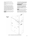
6. Chimney chase concentric venting is permitted for
modules, when stackable, providing concentric
vertical (roof) vent terminals, if level with
each other, are spaced no closer then 12 inches
horizontally.
If vertical vent terminals cannot end in one plane,
they must be spaced no closer then three (3) feet
horizontally.
7.
When individual modules (boilers) are installed in
the same horizontal plane, chimney chase vertical
concentric venting is permitted provided:
a. Sufcient inside space available at the base of
the chimney to install multiple chimney chase
brackets and support elbows.
b. Spacing between adjacent vertical vent terminals
is in accordance with paragraph 6 above.
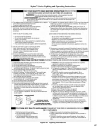
CAUTION
Installing multiple individual module (boiler)
concentric vent terminations too close together
may result in combustion product water vapor
condensation on building surfaces, where
termination are placed, and subsequent frost
damage. To avoid/minimize frost damage extend
the distance from building surfaces to concentric
vent termination end as well as increase the
horizontal distance between adjacent concentric
vent terminations.
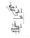
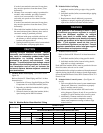
C. Modular Boiler Water Piping – (See Table 19 and
Figure 42)
Refer to Section VI “Water Piping and Trim” of these
Instructions for:
1. Installation of Factory Supplied Piping and Trim
Components for an individual module (boiler).
2. Regarding an individual module (boiler) piping
system specic details.
3. Selection criteria for individual module (boiler)
space heating and/or DHW circulators.
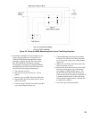
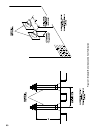
D. Modular Boiler Gas Piping
1. Individual module (boiler) gas pipe sizing specic
details
2.
Individual module (boiler) recommended gas piping.
See Figure 34.
3.
Requirement to install additional gas pressure
regulators to properly regulate gas pressure at the
input of the smallest individual module (boiler).
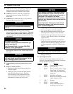
WARNING
If gas pressure in the building is above ½ psig,
an additional gas pressure regulator is required.
Using one additional regulator for multiple
boilers may result in unsafe boiler operation.
The additional regulator must be able to properly
regulate gas pressure at the input of the smallest
boiler. If the regulator cannot do this, two or
more additional regulators are required. Consult
regulator manufacturer and/or local gas supplier
for instructions and equipment ratings.
E. Modular Boiler Electrical
Refer to Section VIII “Electrical” of these Instructions
for:
1.
Individual module (boiler) wiring specic details
2. Individual module (boiler) internal wiring details,
high and low voltage connections
Each individual module (boiler) must be provided with own
fused disconnect and own service switch.
Install modular boiler wiring in accordance with requirements of
authority having jurisdiction. In absence of such requirements,
follow the National Electric Code, NFPA 70 and/or CSA C22.1
Electric Code.
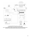
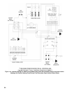
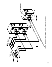
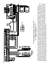
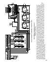
F. Modular Boiler Control Systems – (See Figures 44
and 45)
1. Follow modular boiler control system manufacturer
(Honeywell, Tekmar etc.) instructions to properly
apply a modular control system.
2. Tekmar model 264 and model 265 based control
wiring diagrams (Figures 44 and 45) are provided as
examples of typical modular boiler control system.
3. Additionally, common modular boiler control
systems may use outdoor temperature sensing,
return water temperature sensing or both to stage
modular boilers.
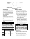
Table 19: Modular Boiler Water Manifold Sizing
Boiler Model
Number of Units
2 3 4 5 6 7 8
Recommended Minimum Common Water Manifold Size (NPT)
ALP080 1¼” 1½” 2” 2½” 2½” 2½” 2½”
ALP105 1½” 2” 2” 2½” 2½” 2½” 3
”
ALP150 2” 2” 2½” 2½” 2½” 3
” 3½”
ALP210 2” 2½” 3
” 3” 3½” 4” 4”
ALP285 2½” 2½” 3
” 3½” 3½” 4” 5”
ALP399 2½” 3
” 3” 4” 4” 5” 5”