


14
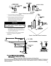
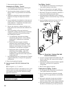
6. Remove the Silicone ue sensor cap from the vent
carton and press onto the two pipe vent system
connector for CPVC/PVC sensor port. Remove
the tape holding the ue sensor and insert the ue
temperature sensor into the ue sensor plug until it
is rmly engaged. See Figure 4.
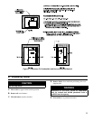
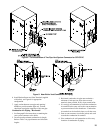
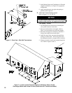
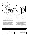
7. Near-Boiler Vent Piping (see Figure 5):
WARNING
All CPVC vent components (supplied with boiler)
must be used for near-boiler vent piping before
transitioning to Schedule 40 PVC pipe (ASTM
2665) components for remainder of vent system.
a. All CPVC vent components (supplied with
boiler), 30” straight and 90° elbow, must be
used for near-boiler piping before transitioning
to Schedule 40 PVC (ASTM 2665) pipe
components for remainder of vent system.
The CPVC 30” straight section may be cut to
accommodate desired vent conguration for
near-boiler piping, provided both pieces are used
in conjunction with the CPVC 90° elbow, before
any PVC components are used. Ensure that the
CPVC elbow is the rst elbow used in the vent
system as it exits the boiler.
b.
Clean all vent and combustion air pipe joints
with primer and secure with transition cement,
(8 oz. bottle of primer and 8 oz. bottle of
transition cement supplied with boiler). Follow
the instructions provided on the primer and
cement.
E. CPVC/PVC Horizontal Venting System
See Figures 3 thru 8.
Vent Piping - Horizontal
1. See Paragraph D for instructions on attaching the
vent system connector to the boiler.
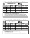
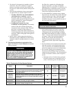
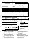
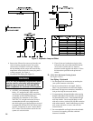
2. Do not exceed maximum vent length. Refer to
Table 7 for pipe diameters and allowable lengths.
3. Horizontal vent pipe must maintain a minimum ¼
inch per foot slope down towards boiler.
4. Use appropriately designed thimbles when passing
through combustible walls (thimble use is optional
for noncombustible walls). Insert thimble through
wall from outside. Secure outside ange to wall
with nails or screws, and seal ID, OD and vent holes
with sealant material. Install inside ange to inside
wall, secure with nails or screws, and seal with
sealant material.
5. For noncombustible wall application when thimble
is not used, size opening such that a minimal
clearance is obtained.
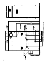
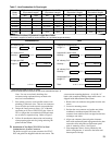
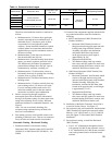
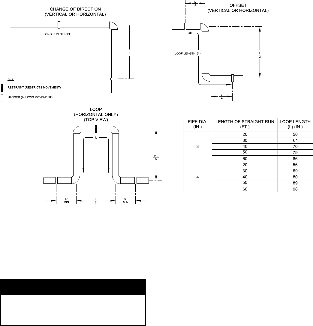
Figure 3: Expansion Loop and Offset