


Continued
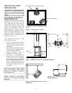
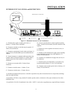
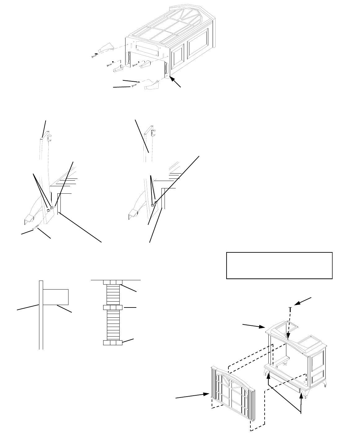
9. Attach stove door by
inserting step bolt through
door hinge pivot hole and
into threaded hole in stove
body (see Figure 8 and
Figure 10). Use an adjustable
wrench or a 12mm socket to
fasten step bolt. Tighten step
bolt until snug. Make sure
door moves freely.
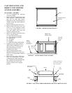
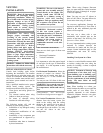
10. Install door catch bolt (M8 x 1.25-55mm
with two M8 hex nuts) into threaded hole on
stove body (see Figures 8 and 10). Use an
adjustable wrench or a 12mm socket. The
catch bolt has two hex nuts attached to it
(see Figure 11). The top nut is a bolt stop
and the bottom nut is for door leveling
adjustment.
11. Check general catch bolt alignment with
door claw. Make final adjustment and door
leveling after stove is in normal standing
position.
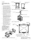
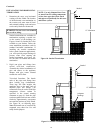
12. Carefully lift stove back up on its four
attached legs.
13. Remove 2 bolts from the bottom of the
stove and discard. Remove the bolt located
in the front top center of the stove to remove
the front panel assembly. (see figure 12)
(NOTE: When removing the front panel
assembly be prepared to hold the front
panel assembly before removing the last
bolt.)
14. If there is a metal plate located across the
inside front of the stove it must be removed.
Remove the 4 screws that secure the plate to
the stove and discard the plate.
BOTTOM OF
STOVE UNIT
WASHERS
BOLTS
Figure 9– Attaching Stove Legs
STOVE DOOR
DOOR
HINGE
STEP
BOLT
BOLT
SHOULDER
THREADED
HOLE
STOVE DOOR
DOOR
HINGE
STEP
BOLT
STOVE BOTTOM
BOLT
SHOULDER
Figure 10-Attaching Lower Stove Door Panel
DOOR
DOOR CLAW
BOLT STOP
ADJUSTING NUT
FIGURE 11 - CATCH BOLT AND
DOOR CLAW ORIENTATION
CATCH BOLT
Front Assembly
Figure 12– Removing Front Panel Assembly
NOTE: IF YOUR CASTING HAS A
DROP BOTTOM– DO NOT INSTALL
– DISCARD THE BOTTOM.
Bolt
Stove Body
Remove 2 Bolts From The
Bottom Front Side Before
Removing The Front Panel
Assembly.
5