


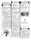
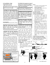
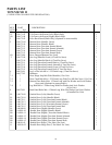
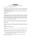
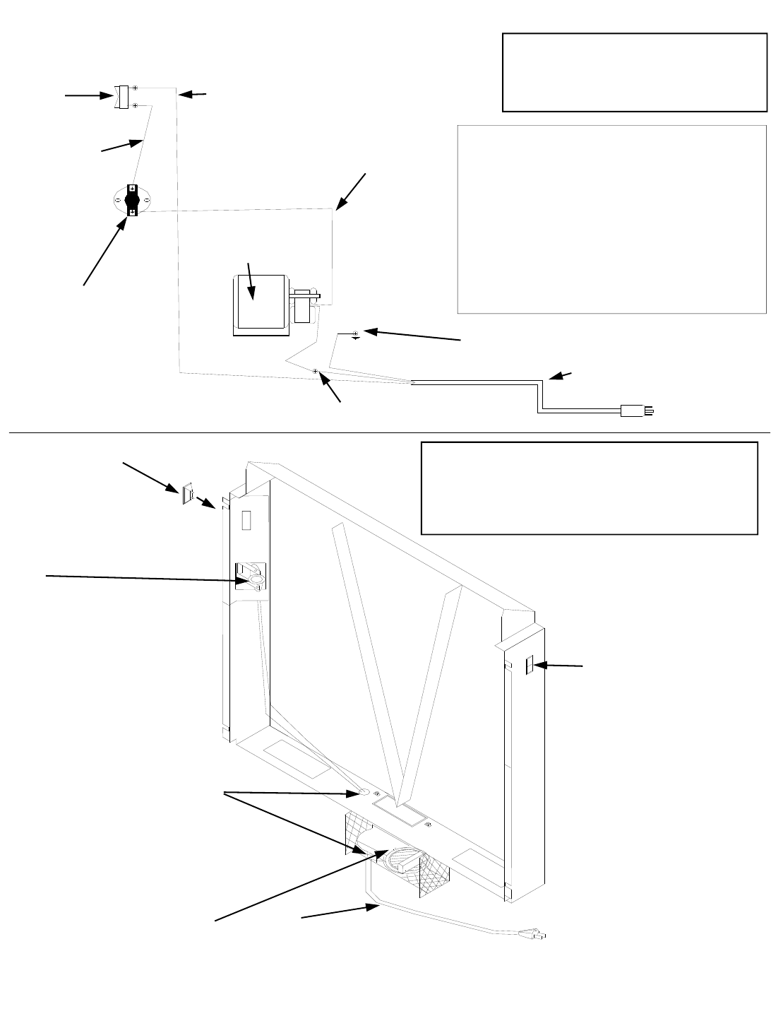
PARTS IDENTIFICATION AND WIRING DIAGRAM
NEW RELEASE
M.B.DATE
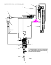
GREEN WIRE (GROUND)
WHITE WIRE (TO MOTOR)
BLACK WIRE (TO (OFF) TOP CONNECTOR
OF ON/OFF SWITCH)
MOTOR TO THERMOSTAT
WIRE FROM
(ON) BOTTOM
CONNECTOR
OF ON/OFF
SWITCH TO
THERMOSTAT
MOTOR
THERMOSTAT
ON/OFF
SWITCH
POWER CORD
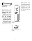
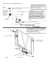
WAR N I N G: ELECTRICAL GROUND-
ING INSTRUCTION: THIS APPLIANCE IS
EQUIPPED WITH A THREE-PRONG
(GROUNDING) PLUG FOR YOUR PROTEC-
TION AGAINST SHOCK HAZARD AND
SHOULD BE PLUGGED DIRECTLY INTO A
PROPERLY GROUNDED THREE-PRONG
RECEPTACLE. DO NOT CUT OR REMOVE
THE GROUNDING PRONG FROM THIS
PLUG.
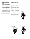
(6) ON/OFF/AUTO
SWITCH LOCATION
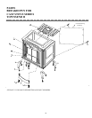
11
12
13
14
15
16* NOT SHOWN
Figure 44
“CAUTION: Label all wires prior to disconnection
when servicing controls. Wiring errors can cause im-
proper and dangerous operation.”
“Verify proper operation after servicing.”
NOTE: If any of the original wire as sup-
plied with the stove must be replaced, it
must be replaced with type 16 ga., 105 C.
rating wire or its equivalent.
31