


Continued
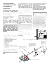
INSTALLING OPTIONAL RECEIVER
AND HAND- HELD REMOTE
CONTROL KIT PART# FDC-504
AND/OR WALL THERMOSTAT
PART# PE 400142 ACCESSORIES
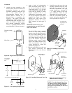
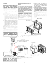
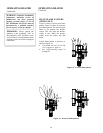
1. First locate the red wire connected to
the control valve and the on /off/auto
switch.
2. Cut the red wire.
3. Next connect one of the wires from
the remote receiver and/or the wall
thermostat to one end of the cut red
wire and secure them together with a
wire nut (not provided) (see Figure
36).
4. Take the remaining end of the cut red
wire and connect the remaining wire
from the remote receiver and/or the
wall thermostat and secure them
together with a wire nut (not provided)
(see Figure 36).
NOTE: Only cut the RED wire. If any
other wire is used the unit will not operate
properly.
* The remote control receiver will Velcro
into the bracket provided on the front of
the burner system beside the control valve.
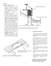
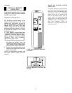
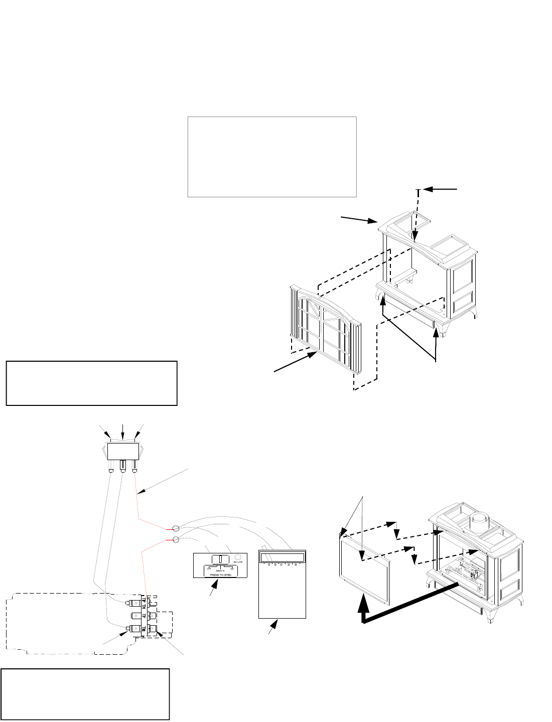
REMOVING/REPLACING GLASS
DOOR
You must remove glass door to install
logs. To remove glass door, you must first
remove the front panel assembly on stove
body if it has been previously installed. If
the front panel assembly is not in place,
proceed to step 2.
WARNING: “Do not operate
appliance with the glass front
removed, cracked or broken.
Replacement of the glass should be
done by a licensed or qualified
service person.”
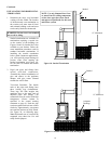
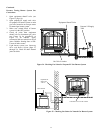
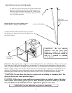
1. Remove 2 bolts from bottom of
stove (if still in place) and one from
the top of stove to remove front
panel (see Figure 37).
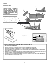
2. Remove the 1/4-20 bolts from the 2
tabs at the top of the glass door
while holding door securely keeping
it from falling forward (see Figure
38).
3. Grasp door by both sides and ease it
upward off of the lower bracket (see
Figure 38).
4. To replace glass door, follow the
above instructions in reverse and see
page 19.
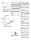
RED WIRE
FOR OPTIONAL REMOTE CONTROL
OR WALL THERMOSTAT
B
L
A
CK
B
L
A
C
K
SIDE VIEW OF VALVE
FRONT TERMINALS
REAR TERMINALS
AUTO/OFF/MANUAL
WARNING: Installation must be
done by a qualified installer familiar
with low voltage wiring procedures.
WARNING: Do not connect this
thermostat to a power source.
Electrical shock and/or fire hazard
will occur.
REMOTE CONTROL
RECEIVER
WALL THERMOSTAT
R
R
T
T
Figure 36-Installing Remote Receiver/Wall
Thermostat
Bolt
Stove Body
Remove 2 Bolts From The
Bottom Front Side Before
Removing The Front Panel
Front Panel Assembly
Figure 37– Removing Front Panel from Stove
1/4-20 Bolts
Figure 38– Removing Glass Cover Door from
Burner System
18