


Continued
3. Attach vent pipe assembly to the
burner system. Set stove in front of its
permanent location to ensure
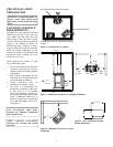
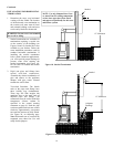
minimum clearances. Mark the wall
for a 10" square hole (for
noncombustible material such as
masonry block or concrete, a 7 ½"
diameter hole is acceptable). See
Figure 21. The center of the hole
should line up with the center line of
the horizontal rigid vent pipe. Cut a
10" x 10" (254mm x 254mm) square
hole through combustible exterior
wall (7 ½" [190mm] diameter hole if
noncombustible). Frame as necessary.
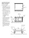
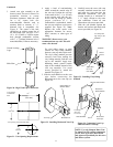
4. Apply a bead of non-hardening
mastic around the outside edge of
the vent cap. Position the vent cap
in the center of the 7 ½" or 10" hole
on the exterior wall with the “up”
on the vent cap facing up. Ensure
proper clearance of 1" to
combustibles is maintained. Attach
the vent cap with four wood screws
supplied (see Figure 22). Note:
Replace the wood screws with
appropriate fasteners for stucco,
brick, concrete, or other types of
siding.
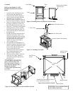
For vinyl siding, stucco, or wood
exterior use vinyl siding standoffs
between vent cap and exterior wall.
The vinyl siding standoff prevents
excessive heat from melting the
vinyl siding material. Bolt the vent
cap to the standoff. Apply non-
hardening mastic around outside
edge of the standoff instead of the
vent cap assembly. Use wood
screws provided to attach the
standoff. See Figure 23.
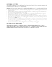
5. Slide the wall thimble over the vent
pipe before connecting the
horizontal run to the vent cap (see
Figure 24).
6. Carefully move the stove with vent
assembly attached toward the wall
and insert the vent pipe into the
horizontal termination. The pipe
overlap should be a minimum of
1 ¼". Apply silicone to the outer
pipe connection. Fasten all vent
connections with screws provided.
7. Slide the wall thimble against the
interior wall surface and attach with
screws provided (see Figure 24).
WARNING: Do not recess vent
termination into any wall. This will
cause a fire hazard.
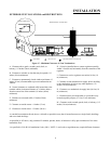
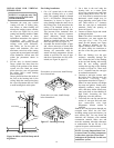
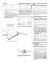
Female Locking
Lugs
Male Slots
Figure 20– Rigid Vent Pipe Connections
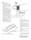
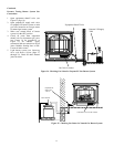
10"
(254 mm)
10"
(254 mm)
Vent Opening
Combustible
Wall
Vent Opening Noncombustible Wall
7 1/2"
(190mm)
Figure 21– Vent Opening Requirements
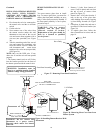
Apply Mastic to
All Four Sides
Wood Screws
Vent Cap
Figure 22– Installing Horizontal Vent Cap
Cut Vinyl Sid-
ing Away to Fit
Standoff
Standoff
Wood
Screws
Nut
Apply Mas-
tic to All
Four Sides
Bolt
Vent
Cap
Figure 23– Installing Vinyl Siding
Standoff
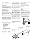
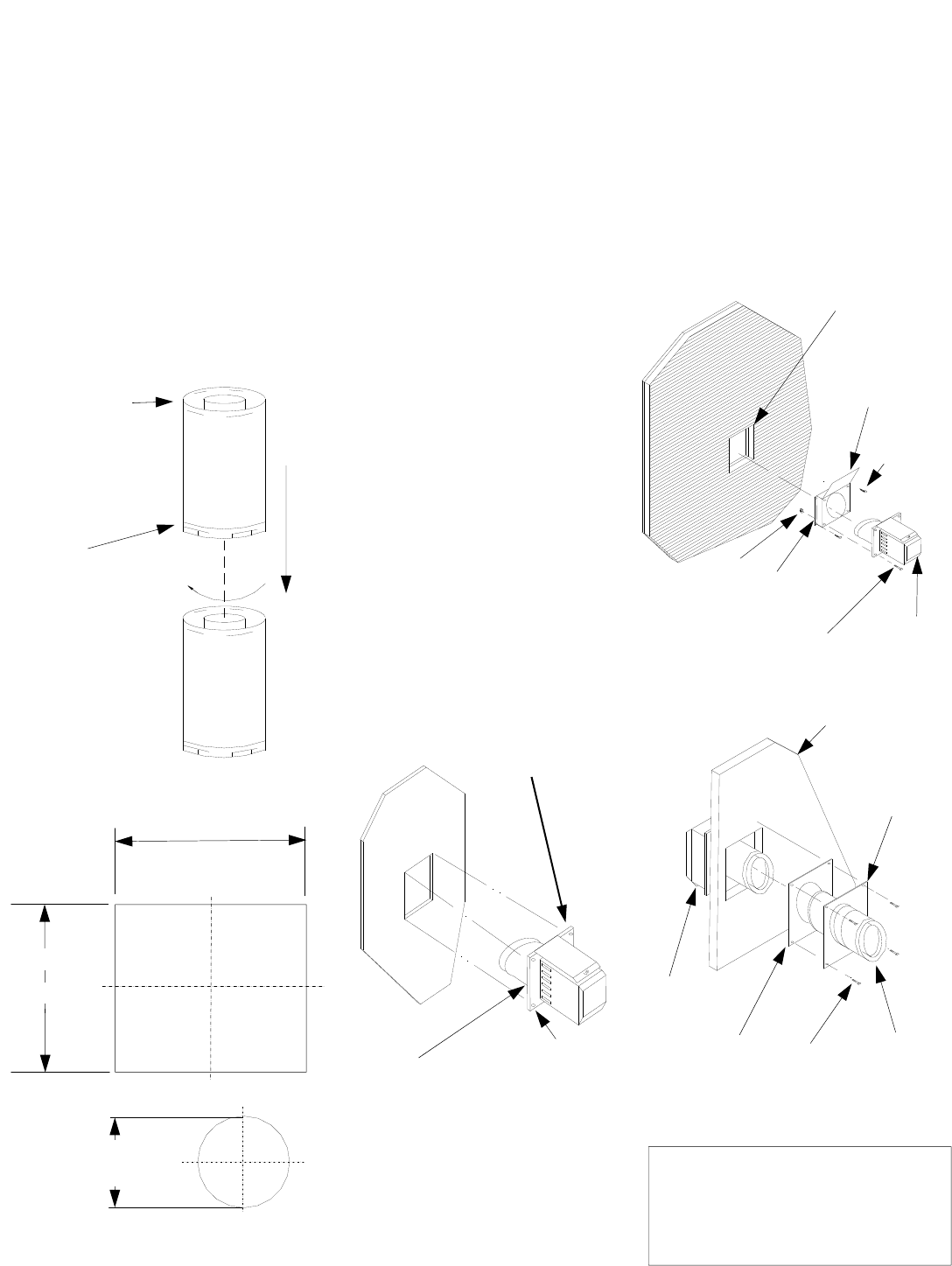
Interior Wall Surface
Decorative
Wall Thimble
Wall Thimble
Screw
Horizontal
Vent Pipe
Vent Cap
(Horizontal
Termination)
Figure 24– Connecting Vent Cap
with Horizontal Vent Pipe
NOTE: Use only Simpson Dura-Vent
or AmeriVent GS venting components
or kits, these types have been tested
and approved specifically for this stove
and burner system.
11