


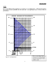
Continued
INSTALLING DIRECT-VENT
BURNER SYSTEM INTO STOVE
BODY
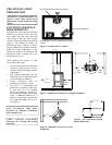
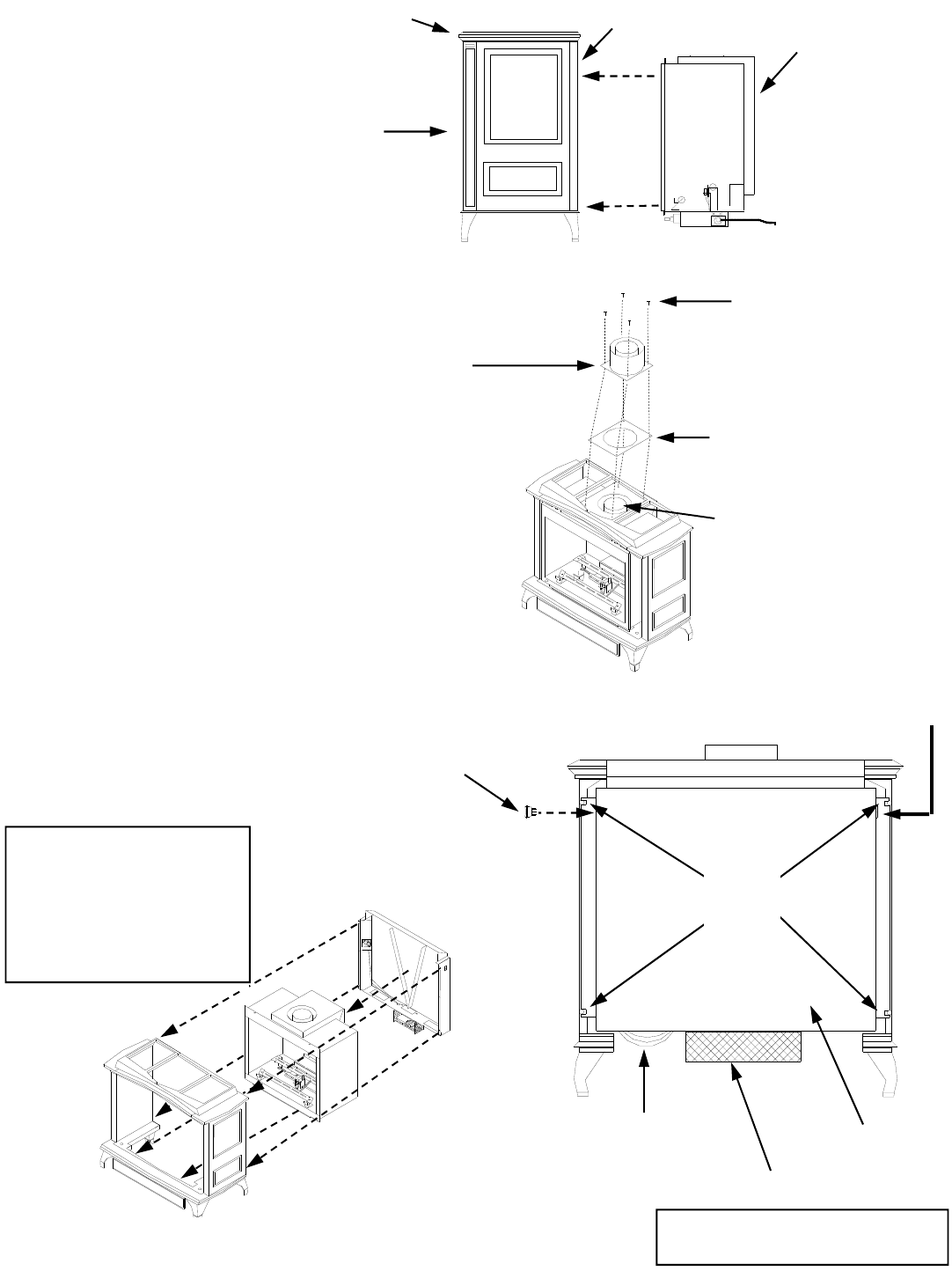
1. Carefully remove the burner system
(fire box) from the shipping box.
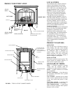
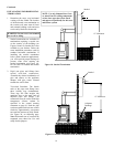
2. Carefully lift the burner system and
place it into the stove body from the
rear of the stove (see figure 13).
3. Slide the burner system to the front of
the stove body (see figures 13 and 14).
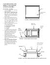
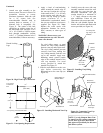
4. Place the vent gasket on the outside of
the burner system box over the vent
hole and align the holes(see figure 15).
5. Place the 7" vent collar over the gasket
and align the holes. Secure with hex
head screws provided (see figure 15).
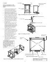
6. Next remove the blower system from
the shipping box .
7. Find the on/off/auto switch and wires
attached to the burner system. You
will need to unplug the wires from the
switch and place the switch in the slot
provided on the side of the blower
system (see figure 16 and figures
43,44 on pages 30,31) .
8. Next push the wires through the 5/8"
round hole located in the bottom of the
blower system and reconnect the wires
to the switch using the labels on the
wires to insure the wires are
reconnected to the correct terminals
(see wiring diagram pages 30,31
figures 43,44)(see figure 16).
9. Secure the blower system to the rear
of the cast stove body with the 4
10mm bolts provided with the stove
(see figure 16).
Front
Stove Body
Burner System (Direct
Vent Fire Box)
Rear
Figure 13-Installing Burner System into Cast Stove body.
Figure 14– Installing Burner System and Blower System.
4 Hex Head Screws
7" Vent Collar
Vent Collar Gasket
Burner System Vent Opening
Figure 15– Installing Vent Collar
On/Off/Auto
Switch
Blower System
Labeled Wires from Burner System
Go to On/Off/Auto Switch
On/Off Switch
For Blower
Blower Motor
4 10mm
Bolts
Figure 16-Secure Blower System
WARNING: Never touch the blower
wheel while in operation.
“CAUTION: Label all wires
prior to disconnection when
servicing controls. Wiring er-
rors can cause improper and
dangerous operation.”
“Verify proper operation after
servicing.”
6