


Continued
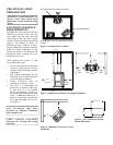
INSTALLATION FOR HORIZONTAL
TERMINATION
1. Determine the route your horizontal
venting will take. Note: The location
of the horizontal vent termination on
the exterior wall must meet all local
and national building codes and must
not be easily blocked or obstructed.
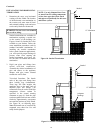
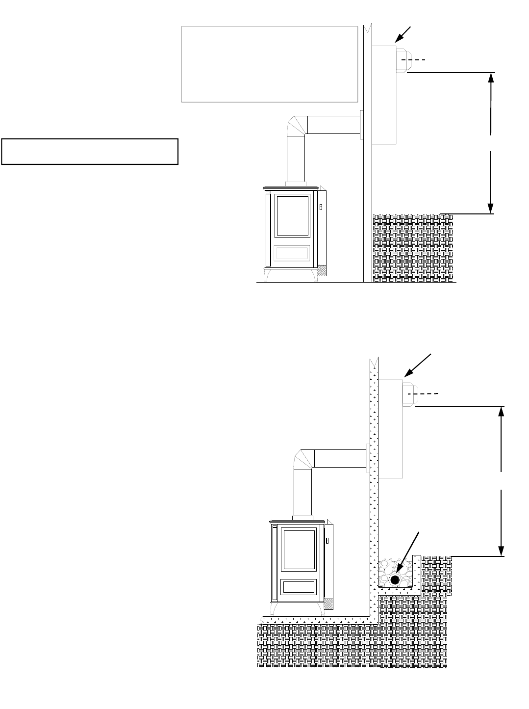
Snorkel terminations are available for
terminations requiring a vertical rise
on the exterior of the building (see
Figures 18 and 19). Snorkel kit is also
available at your dealers. Follow the
same installation procedures used for
standard horizontal terminations. If
installing the snorkel termination
below grade (basement applications),
you must provide proper drainage to
prevent water from entering the
snorkel termination (see Figure 19).
Do not back fill around the snorkel
termination.
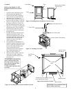
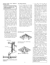
2. Rigid vent pipes and fittings have
special twist-lock connections.
Assemble the desired combination of
pipe and elbows to the appliance
adaptor with pipe seams oriented
towards the wall or floor.
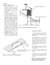
Twist-lock Procedure: The female
ends of the pipes and fittings have
three locking lugs (indentations).
These lugs will slide straight into
matching slots on the male ends of
adjacent pipes and fittings. (All
connections must be sealed with high
temperature silicone sealant as
specified in the second warning
statement on page 9). Push the pipe
sections together and twist one section
clockwise approximately one-quarter
turn until the sections are fully locked.
See Figure 20, on following page.
Note: Horizontal runs of vent must be
supported every three feet. Use wall
straps for this purpose.
WARNING: Do not recess vent terminal
into a wall or siding.
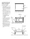
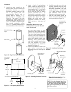
Snorkel
12" Minimum
Figure 18– Snorkel Termination
Snorkel
12" Minimum
Adequate
Drainage
Figure 19– Snorkel Termination with Drainage Pipe
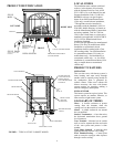
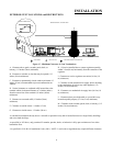
NOTE: Use only Simpson Dura-Vent
or AmeriVent GS venting components
or kits, these types have been tested
and approved specifically for this stove
and burner system.
10