


—
8
—
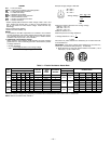
VI. STEP 6 — MAKE ELECTRICAL CONNECTIONS
A. Field Power Supply
Unit is factory wired for voltage shown on nameplate.
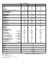
When installing units, provide a disconnect, per NEC
(National Electrical Code) requirements, of adequate size
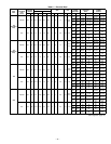
(Table 2). Electrical heater data is shown in Table 3.
All field wiring must comply with NEC and local require-
ments.
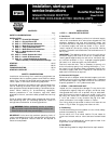
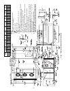
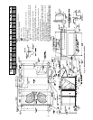
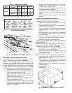
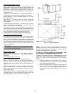
Route power lines through control box access panel or unit
basepan (Fig. 4 and 5) to connections as shown on unit wir-
ing diagram and Fig. 11.
Operating voltage to compressor must be within voltage
range indicated on unit nameplate. On 3-phase units, volt-
ages between phases must be balanced within 2% and the
current must be balanced within 10%.
Use the following formula to determine the percentage of
voltage imbalance.
Percentage of Voltage Imbalance
EXAMPLE: Supply voltage is 460-3-60.
AB = 452 v
BC = 464 v
AC = 455 v
Determine maximum deviation from average voltage:
(AB) 457 – 452 = 5 v
(BC) 464 – 457 = 7 v
(AC) 457 – 455 = 2 v
Maximum deviation is 7 v.
Determine percent voltage imbalance:
= 1.53%
This amount of phase imbalance is satisfactory as it is below
the maximum allowable 2%.
IMPORTANT: If the supply voltage phase imbalance is
more than 2%, contact your local electric utility company
immediately.
Unit failure as a result of operation on improper line voltage
or excessive phase imbalance constitutes abuse and may
cause damage to electrical components.
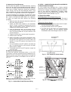
B. Field Control Wiring
Install a Bryant-approved accessory thermostat assembly
according to the installation instructions included with the
accessory. Locate thermostat assembly on a solid wall in the
conditioned space to sense average temperature.
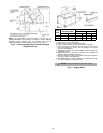
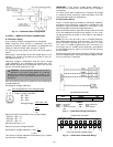
Route thermostat cable or equivalent single leads of colored
wire from subbase terminals through conduit in unit to low-
voltage connections as shown on unit label wiring diagram
and in Fig. 12.
NOTE: For wire runs up to 50 ft, use no. 18 AWG (American
Wire Gage) insulated wire (35 C minimum). For 50 to 75 ft,
use no. 16 AWG insulated wire (35 C minimum). For over
75 ft, use no. 14 AWG insulated wire (35 C minimum). All
wire larger than no. 18 AWG cannot be directly connected to
the thermostat and will require a junction box and splice at
the thermostat.
Set heat anticipator settings as indicated in Table 4. Settings
may be changed slightly to provide a greater degree of com-
fort for a particular installation.
CAUTION: The correct power phasing is critical in
the operation of the scroll compressors. An incorrect
phasing will cause the compressor to rotate in the
wrong direction. This may lead to premature compres-
sor failure.
= 100 x
max voltage deviation from average voltage
average voltage
Average Voltage =
455 + 464 + 455
3
=
1371
3
= 457
Percentage of Voltage Imbalance = 100 x
7
457
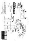
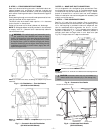
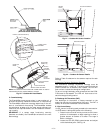
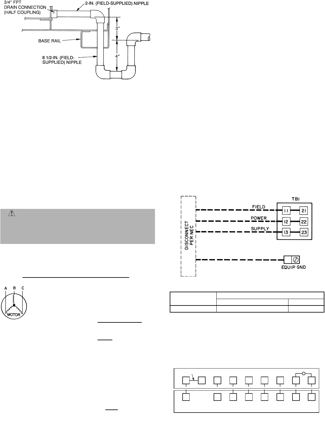
Fig. 10 — Condensate Drain Piping Details
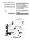
RH
RC
Y1 Y2
W1
W2
GC
X
L
X
C
G
W2
W1Y2
Y1
R
REMOVABLE JUMPER
RED
BLU
PNK
ORN
VIO
BLK
BRN
WHT
THERMOSTAT ASSEMBLY
TB1 MAXIMUM WIRE SIZE
LEGEND
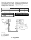
Fig. 11 — Field Power Wiring Connections
UNIT
551A
VOLTAGE
208/230 460
All
350 kcmil 2/0
EQUIP—
Equipment
NEC —
National Electrical
GND —
Ground Code
kcmil —
Thousand Circular
TB —
Terminal Block
Mils
UNIT LOW-VOLTAGE CONNECTIONS
Fig. 12 — Field Control Thermostat Wiring