


—
19
—
If outdoor air alone cannot satisfy the cooling requirements
of the conditioned space, and the OAT is above the MECH
CLG LOCKOUT set point, the EconoMi$er integrates free
cooling with mechanical cooling. This is accomplished by the
strategies below.
NOTE: Compressors have a two-minute Minimum On and
Minimum Off, which are accomplished by the strategies
below.
1. If Y1 is energized, and the room thermostat calls for
Y2 (2-stage thermostat), the compressor and OFC are
energized. The position of the EconoMi$er damper is
maintained at its current value.
2. If Y1 is energized for more than 20 minutes, and Y2 is
not energized (whether or not a 2-stage thermostat is
used), the compressor and OFC are energized. The
position of the EconoMi$er damper is maintained at
its current value.
3. If Y1 is energized, and compressor no. 1 is already
energized (see Step 2) and the room thermostat calls
for Y2, compressor no. 1 continues to operate. If Y2
remains energized for more than 20 minutes, com-
pressor no. 2 is energized.
NOTE: Compressor no. 2 cannot be energized unless there is
a signal for Y2 from the space thermostat.
4. If compressor no. 2 is energized, and the Y2 signal
from the thermostat is satisfied, compressors 1 and 2
are deenergized. Re-asserting Y2 will start compres-
sor no. 1 and (after a 20-minute interstage delay)
compressor no. 2.
5. If compressor no. 1 is energized and the thermostat is
satisfied, compressor no. 1, the OFM, and IFM are
deenergized and the EconoMi$er modulates closed.
When the OAT is below the MECH CLG LOCKOUT set
point, the compressors remain off.
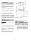
D. Freeze Protection Thermostat(s)
A freeze protection thermostat (FPT) is located on the top
and bottom of the evaporator coil. It detects frost build-up
and turns off the compressor, allowing the coil to clear. Once
frost has melted, the compressor can be reenergized by reset-
ting the compressor lockout.
E. Heating, Units With EconoMi$er (If Accessory or
Optional Heater is Installed)
When the room thermostat calls for heat, the heating con-
trols are energized as described in the Heating, Units With-
out EconoMi$er section. The IFM is energized and the
EconoMi$er damper modulates to the minimum position.
When the thermostat is satisfied, the damper modulates
closed.
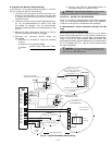
F. Units With Perfect Humidity™ Dehumidification Package
When thermostat calls for cooling, terminals G and Y1 and/
or Y2 and the compressor contactor C1 and/or C2 are ener-
gized. The indoor (evaporator) fan motor (IFM), compressors,
and outdoor (condenser) fan motors (OFM) start. The OFMs
run continuously while the unit is in cooling. As shipped
from the factory, both Perfect Humidity dehumidification cir-
cuits are always energized.
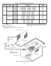
If Perfect Humidity circuit modulation is desired, a field-
installed, wall-mounted humidistat is required. If the Perfect
Humidity humidistat is installed and calls for the Perfect
Humidity subcooler coil to operate, the humidistat internal
switch closes. This energizes the 3-way liquid line solenoid
valve coils (LLSV1 for circuit 1 and LLSV2 for circuit 2) of
the Perfect Humidity circuits, forcing the warm liquid refrig-
erant of the liquid line to enter the subcooler coils. See
Fig. 29.
As the warm liquid passes through the subcooler coils, it is
exposed to the cold supply airflow coming off the evaporator
coils and the liquid is further cooled to a temperature
approaching the evaporator coil leaving-air temperature.
The state of the refrigerant leaving the subcooler coils is a
highly subcooled liquid refrigerant. The liquid then enters a
thermostatic expansion valve (TXV) where the liquid is
dropped to the evaporator pressure. The TXVs can throttle
the pressure drop of the liquid refrigerant and maintain
proper conditions at the compressor suction valves over a
wide range of operating conditions. The liquid proceeds to
the evaporator coils at a temperature lower than normal
cooling operation. This lower temperature is what increases
the latent and sensible capacity of the evaporator coils.
The 2-phase refrigerant passes through the evaporators and
is changed into a vapor. The air passing over the evaporator
coils will become colder than during normal operation as a
result of the colder refrigerant temperatures. However, as it
passes over the subcooler coils, the air will be warmed,
decreasing the sensible capacity and reducing the sensible
heat of the roof- top unit.
As the refrigerant leaves the evaporator, the refrigerant
passes a subcooler control low-pressure switch (S-LPS1 for
circuit 1 or S-LPS2 for circuit 2) in the suction line. This low-
pressure switch will deactivate the Perfect Humidity pack-
age when the suction pressure reaches 60 psig. The sub-
cooler control low-pressure switch is an added safety device
to protect against evaporator coil freeze-up during low ambi-
ent operation. The subcooler control low-pressure switch will
only deactivate the 3-way liquid line solenoid valve in the
Perfect Humidity circuit. The compressors will continue to
run as long as there is a call for cooling, regardless of the
position of the subcooler control low-pressure switch. The
3-way solenoid valve and the Perfect Humidity package will
be reactivated only when the call for cooling has been satis-
fied, the subcooler control low-pressure switch has closed
above 80 psig, and a new call for cooling exists. The crank-
case heaters on the scroll compressors provide additional
protection for the compressors due to the additional refriger-
ant charge in the subcooler.
When the humidistat is satisfied, the humidistat internal
switch opens, cutting power to and deenergizing the LLSVs.
The refrigerant is routed back through the evaporators and
the subcooler coils are removed from the refrigerant loops.
When the thermostat is satisfied, C1 and C2 are deenergized
and the compressors, IFM, and OFMs shut off. If the thermo-
stat fan selector switch is in the ON position, the IFM will
run continuously.