


—
13
—
C. Commissioning
The EconoMi$er saves energy when it uses outdoor air to
provide free cooling instead of mechanical air conditioning.
The EconoMi$er switchover strategy determines if the out-
door air is suitable for free cooling. The EconoMi$er chooses
the switchover strategy with the most energy savings, pro-
vided that the required sensors are connected and function-
ing normally.
IMPORTANT: If a sensor stops functioning normally
(becomes unreliable), the EconoMi$er switches to the next
best strategy.
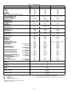
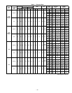
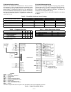
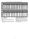
Refer to Table 5 to determine the sensors required for each
strategy.
Differential Enthalpy Switchover Strategy
The differential enthalpy switchover strategy must be
selected manually, if required. To enable, press and hold the
CONFIG button for 30 seconds, then release. The LED will
flash twice to indicate the change of configuration.
To return to single enthalpy mode, press and hold the CON-
FIG button for 30 seconds. The LED will flash once to indi-
cate the change of configuration.
D. Discharge Air Thermistor (DAT)
The discharge air thermistor is factory-mounted on the
supply-fan housing in the fan section of the unit. The DAT is
factory-wired to the EconoMi$er Control Module.
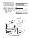
E. CO
2
Control Setup
If a CO
2
sensor is not being used, proceed to the next section.
If a CO
2
sensor is being used, perform the following:
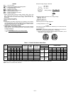
1. Determine the value at which you want the minimum
position of the dampers to begin opening to allow a
greater amount of outdoor air to enter. The range is
800 to 1,400 ppm.
2. Locate the CO
2
SP (PPM) potentiometer and adjust
to the desired set point. See Fig. 16.
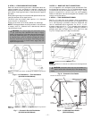
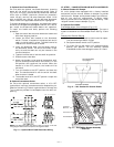
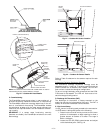
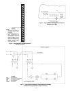
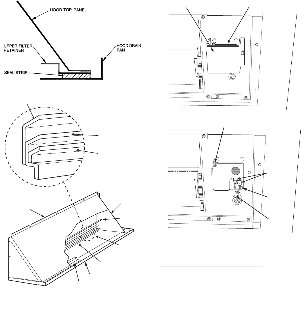
Fig. 19 — Seal Strip Location
(Air Hood Cross-Sectional View)
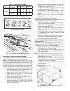
NOTE:
The outdoor-air hood comes with a baffle which is used on
180 and 240 units only; discard baffle for 155 units.
Fig. 20 — Outdoor-Air Hood Details
HOOD TOP
PANEL
HOOD SIDE
PANELS (2)
BAFFLE
(180 AND
240 ONLY)
LOWER
FILTER
RETAINER
FILTER SUPPORT
BRACKET
HOOD DRAIN PAN
UPPER FILTER RETAINER
BAFFLE (180 AND 240 ONLY)
LOWER FILTER
RETAINER
FILTER SUPPORT
BRACKET
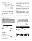
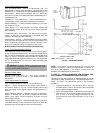
SENSOR
COVER
OUTSIDE AIR SENSOR
MOUNTING
SCREW
MOUNTING SCREW
WIRING
HARNESS
SENSOR
WIRING
CONNECTIONS
Fig. 22 — Outdoor-Air Sensor Details
Fig. 21 — Outdoor-Air Sensor Location