


—
30
—
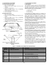
E. Freeze Protection Thermostat (FPT)
An FPT is located on the top and bottom of the evaporator
coil. It detects frost build-up and turns off the compressor,
allowing the coil to clear. Once the frost has melted, the com-
pressor can be reenergized.
XII. RELIEF DEVICES
All units have relief devices to protect against damage from
excessive pressures (e.g., fire). These devices protect the high
and low side.
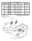
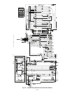
XIII. CONTROL CIRCUIT, 24-V
This control circuit is protected against overcurrent by a
3.2-amp circuit breaker. Breaker can be reset. If it trips,
determine cause of trouble before resetting. See Fig. 36 and
37.
XIV. REPLACEMENT PARTS
A complete list of replacement parts may be obtained from
any Bryant distributor upon request.
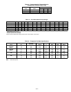
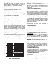
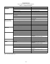
XV. ECONOMI$ER LEDs
The EconoMi$er control module has LEDs for diagnostic
purposes. The flash code identification is shown in Table 17.
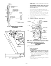
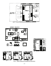
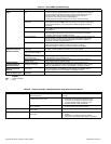
XVI. OPTIONAL HINGED ACCESS DOORS
When the optional service package is ordered or the if the
hinged access doors option is ordered, the unit will be pro-
vided with external and internal hinged access doors to facil-
itate service.
Four external hinged access doors are provided. All external
doors are provided with 2 large
1
/
4
turn latches with folding
bail-type handles. (Compressor access doors have one latch.)
A single door is provided for filter and drive access. One door
is provided for control box access. The control box access door
is interlocked with the non-fused disconnect which must be
in the OFF position to open the door. Two doors are provided
for access to the compressor compartment.
Two internal access doors are provided inside the filter/drive
access door. The filter access door (on the left) is secured by 2
small
1
/
4
turn latches with folding bail-type handles. This
door must be opened prior to opening the drive access door.
The drive access door is shipped with 2 sheet metal screws
holding the door closed. Upon initial opening of the door,
these screws may be removed and discarded. The door is
then held shut by the filter access door, which closes over it.
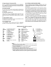
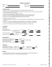
LEGEND AND NOTES FOR FIG. 36 AND 37
LEGEND
AHA —
Adjustable Heat Anticipator
BRK W/AT —
Breaks with Amp Turns
C —
Contactor, Compressor
CAP —
Capacitor
CB —
Circuit Breaker
CC —
Cooling Compensator
CH —
Crankcase Heater
CLO —
Compressor Lockout
COMP —
Compressor Motor
CR —
Control Relay
DAT —
Discharge Air Thermistor
DM —
Damper Motor
DU —
Dummy Terminal
EC —
Enthalpy Control
EQUIP —
Equipment
FL —
Fuse Link
FPT —
Freeze Protection Thermostat
FU —
Fuse
GND —
Ground
HC —
Heater Contactor
HPS —
High-Pressure Switch
HTR —
Heater
IFC —
Indoor-Fan Contactor
IFCB —
Indoor-Fan Circuit Breaker
IFM —
Indoor-Fan Motor
IFR —
Indoor-Fan Relay
L —
Light
LPS —
Low-Pressure Switch
LS —
Limit Switch
NEC —
National Electrical Code
OAT —
Outdoor-Air Thermostat
OFC —
Outdoor-Fan Contactor
OFM —
Outdoor-Fan Motor
OP —
Overcurrent Protection
PL —
Plug Assembly
PRI —
Primary
QT —
Quadruple Terminal
SW —
Switch
TB —
Terminal Block
TC —
Thermostat Cooling
TH —
Thermostat Heating
TRAN —
Transformer
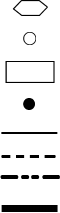
Terminal (Marked)
Terminal (Unmarked)
Terminal Block
Splice
Factory Wiring
Field Wiring
Option/Accessory Wiring
To indicate common potential
only; not to represent wiring.
NOTES:
1. Compressor and/or fan motor(s) thermally protected; 3-phase motors protected
against primary single-phasing conditions.
2. If any of the original wire furnished must be replaced, it must be replaced with type
90° C wire or its equivalent.
3. Jumpers are omitted when unit is equipped with EconoMi$er.
5. IFCB must trip amps is equal to or less than 140% FLA.
6. The CLO locks out the compressor to prevent short cycling on compressor over-
load and safety devices. Before replacing CLO, check these devices.
7. Number(s) indicates the line location of used contacts. A bracket over (2) numbers
signifies a single-pole, double-throw contact. An underlined number signifies a
normally closed contact. Plain (no line) number signifies a normally open contact.