


—
28
—
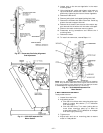
VI. CONDENSER-FAN ADJUSTMENT
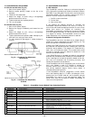
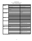
A. 551A155 and 180 Units (Fig. 33)
1. Shut off unit power supply.
2. Remove access panel(s) closest to the fan to be
adjusted.
3. Loosen fan hub setscrews.
4. Adjust fan height on shaft using a straightedge
placed across the fan orifice.
5. Tighten setscrews and replace panel(s).
6. Turn on unit power.
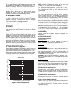
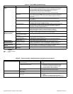
B. 551A240 Units (Fig. 34)
1. Shut off unit power supply.
2. Remove fan top-grille assembly and loosen fan hub
screws.
3. Adjust fan height on unit, using a straightedge
placed across the fan orifice.
4. Tighten setscrews and replace rubber hubcap to pre-
vent hub from rusting to motor shaft.
5. Fill hub recess with permagum if rubber hubcap is
missing.
VII. ECONOMI$ER ADJUSTMENT
A. LED Indication
The EconoMi$er controller features an onboard diagnostic
LED (light-emitting diode) that flashes to indicate its status.
See Table 17 for flash codes. The controller also has terminal
connections (REM LED) for remotely mounting an LED, if
desired. The flash code priorities are as follows:
1. On/Off or continuous flash
2. Critical fault
3. Non-critical fault
If any sensors are opened, shorted, or removed, the
EconoMi$er determines whether the failure is critical or
non-critical and flashes the appropriate code. If a non-critical
sensor fault occurs (i.e., outdoor air humidity), the
EconoMi$er automatically reconfigures its control strategy
to a more appropriate mode. If a critical sensor fault occurs
(i.e., supply air sensor), the EconoMi$er reverts to a safe
mode of operation until the sensor problem is resolved.
B. Manual Configuration Pushbutton
The EconoMi$er controller also features an onboard button
(CONFIG) to help troubleshoot the system. See Fig. 16. The
button can perform 3 different functions.
Pressing the CONFIG button for more than three seconds,
but less than ten seconds and then releasing will start the
automatic test procedure. The damper will modulate fully
open, wait, and modulate closed. This process takes three
minutes to complete. Use this feature to determine if the
actuator can be commanded.
If the CONFIG button is pressed and held for ten seconds
and less than 30 seconds then released, the EconoMi$er con-
troller reconfigures its mode of operation based on the sen-
sors that are connected and functioning normally, and
cancels the automatic test procedure.
If the EconoMi$er controller recognized a non-critical sensor
fault, and flashed a code (i.e., FLASH 6, outdoor air
humidity sensor fault) the FLASH CODE will be cleared,
and normal operation begins. Ensure faulty sensor is
removed before clearing faults.
If the EconoMi$er controller recognizes a critical sensor
fault, and flashes a code (i.e., FLASH 4, discharge air ther-
mostat fault) the FLASH code will not be cleared, and the
EconoMi$er will remain in the safe operation mode. The
sensor fault must be corrected to enable EconoMi$er to
revert to normal operation.
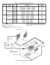
Table 17 — EconoMi$er Control Module Flash Code Identification
FLASH CODE CAUSE ACTION TAKEN BY ECONOMI$ER
Constant On
Normal operation Normal operation.
Constant Off
No power No operation.
Continuous
Flash
CONFIG button pushed and held
between 3 and 9 seconds
Outdoor air damper is stroked fully open, then closed
(automatic test procedure takes 3 minutes to complete).
Critical Fault
Flash One
Control board fault System shutdown.
Flash Two
Thermostat fault (i.e., Y2 without Y1) System shutdown until corrected.
Flash Three
Actuator fault Revert to mechanical cooling only.
Flash Four
Discharge air thermistor fault
Continue operation with damper at minimum position.
Revert to mechanical cooling only.
Flash Five
Outdoor air temperature sensor fault
Continue operation with damper at minimum position.
Disable mechanical cooling lockout.
Non-Critical Fault
Flash Six
Outdoor air humidity sensor fault Continue operation with dry bulb or dry bulb differential switchover.
Flash Seven
Return air temperature sensor fault
Continue operation with single enthalpy EconoMi$er
switchover or dry bulb EconoMi$er switchover (without
humidity sensor).
Flash Eight
Return air humidity sensor fault
Continue operation with single enthalpy, differential dry
bulb, or dry bulb EconoMi$er switchover.
Flash Nine
Carbon Dioxide (CO
2
) sensor fault Continue operation without ventilation control.
Flash Ten
Onboard adjustment potentiometer fault Continue operation with default potentiometer settings.
NOTE: Dimensions are in inches.
Fig. 34 — Condenser-Fan Adjustment,
551A240
NOTE: Dimensions are in inches).
Fig. 33 — Condenser-Fan Adjustment,
551A155,180