


—
11
—
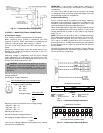
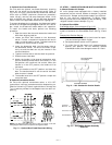
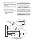
C. Optional Non-Fused Disconnect
On units with the optional non-fused disconnect, incoming
power will be wired into the disconnect switch. Refer to
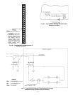
Fig. 13 for wiring for 100 and 200 amp disconnect switches.
Units with an MOCP (maximum overcurrent protection)
under 100 will use the 100 amp disconnect switch. Units
with an MOCP over 100 will use the 200 amp disconnect
switch. Refer to the applicable disconnect wiring diagram.
To prevent breakage during shipping, the disconnect handle
and shaft are shipped and packaged inside the unit control
box. Install the disconnect handle before unit operation.
To install the handle and shaft, perform the following
procedure:
1. Open the control box door and remove the handle and
shaft from shipping location.
2. Loosen the Allen bolt located on the disconnect
switch. The bolt is located on the square hole and is
used to hold the shaft in place. The shaft cannot be
inserted until the Allen bolt is moved.
3. Insert the disconnect shaft into the square hole on
the disconnect switch. The end of the shaft is spe-
cially cut and the shaft can only be inserted in the
correct orientation.
4. Tighten the Allen bolt to lock the shaft into position.
5. Close the control box door.
6. Attach the handle to the external access door with
the two screws provided. When the handle is in the
ON position, the handle will be vertical. When the
handle is in the OFF position, the handle will be
horizontal.
7. Turn the handle to the OFF position and close the
door. The handle should fit over the end of the shaft
when the door is closed.
8. The handle must be in the OFF position to open the
control box door.
D. Optional Convenience Outlet
On units with optional convenience outlet, a 115-v GFI
(ground fault interrupt) convenience outlet receptacle is pro-
vided for field wiring. Field wiring should be run through the
7
/
8
-in. knockout provided in the basepan near the return air
opening.
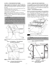
VII. STEP 7 — MAKE OUTDOOR-AIR INLET ADJUSTMENTS
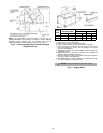
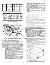
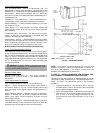
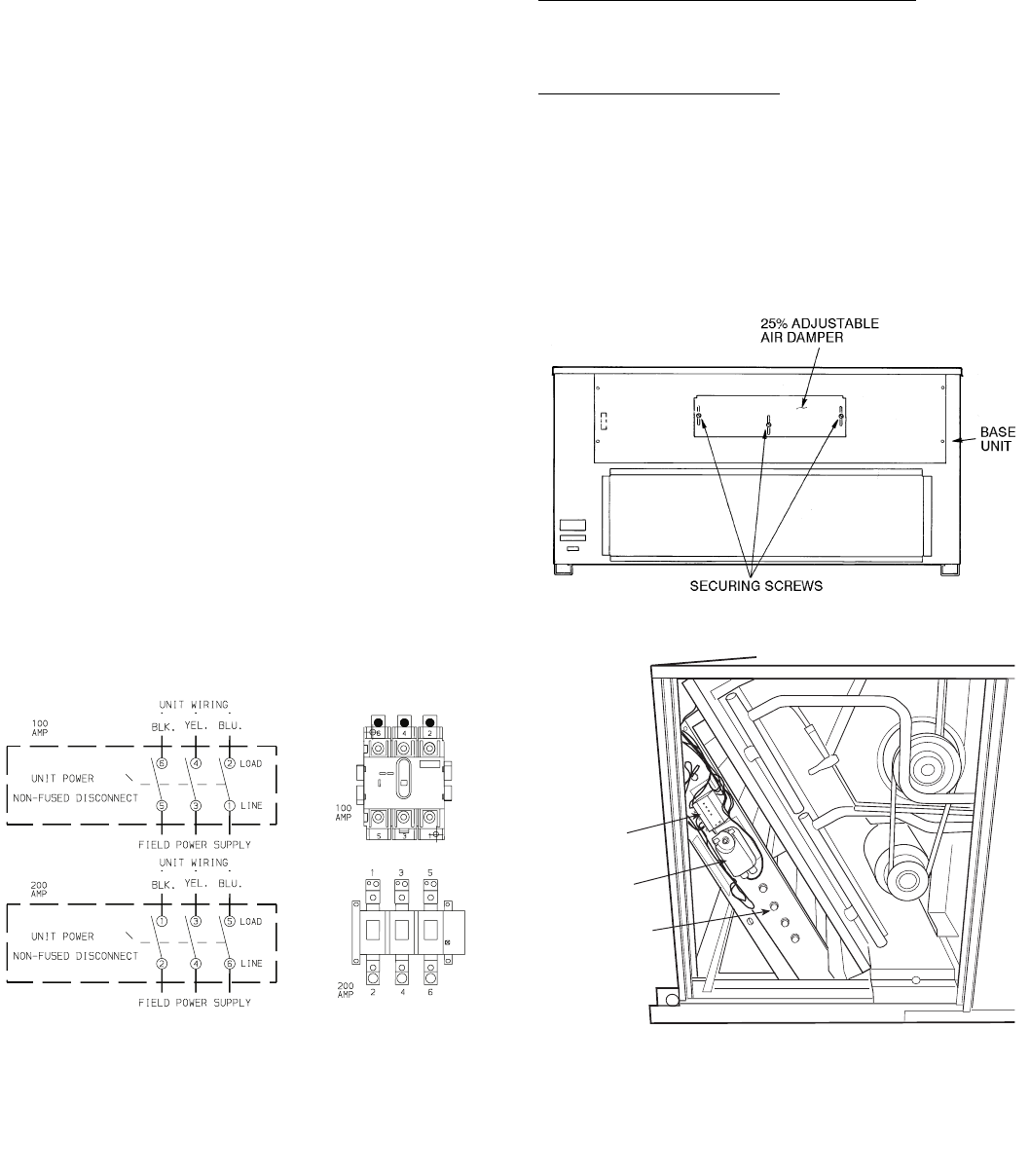
A. Manual Outdoor-Air Damper
All units (except those equipped with a factory-installed
economizer) have a manual outdoor-air damper to provide
ventilation air. Damper can be preset to admit up to 25% out-
door air into return-air compartment. To adjust, loosen
securing screws and move damper to desired setting. Then
retighten screws to secure damper (Fig. 14).
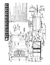
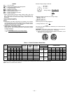
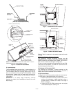
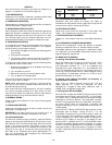
B. Optional EconoMi$er
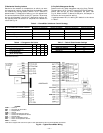
EconoMi$er Motor Control Module (Fig. 15-17)
Set the ECONSP dial to the ‘‘D’’ setting (Fig. 16). The control
module is located on the EconoMi$er motor. See Fig. 15 and
17.
Damper Vent Position Setting
1. Set fan switch at ON position (continuous fan opera-
tion) and close night switch if used.
2. Set system selector switch to OFF position.
3. Turn Min Pos (%) dial slowly until dampers assume
desired vent position. Do not manually operate
EconoMi$er motor since damage to motor will result.
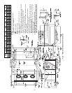
5L3 3L2 1L1 LINE
6T3 4T2 2T1 LOAD
NOTE:
The disconnect takes the place of TB-1 as shown on the unit
wiring diagram label and the component arrangement label.
Fig. 13 — Optional Non-Fused Disconnect Wiring
CONTROL
MODULE
ACTUATOR
ECONOMI$ER
Fig. 14 — 25% Outdoor-Air Section Details
Fig. 15 — EconoMi$er Damper Assembly
— End View