


—
29
—
If the CONFIG button is pressed and held for more than
30 seconds and released, the EconoMi$er controller will
enable the enthalpy comparison strategy (with outdoor air
enthalpy and return air enthalpy sensors installed).
VIII. POWER FAILURE
Dampers have a spring return. In event of power failure,
dampers will return to fully closed position until power is
restored. Do not manually operate damper motor.
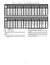
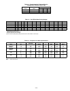
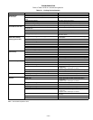
IX. REFRIGERANT CHARGE
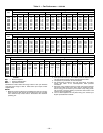
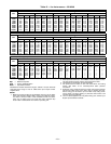
Amount of refrigerant charge is listed on unit nameplate and
in Table 1. Refer to Carrier GTAC II; Module 5; Charging,
Recovery, Recycling, and Reclamation section for charging
methods and procedures. Unit panels must be in place when
unit is operating during charging procedure.
NOTE: Do not use recycled refrigerant as it may contain
contaminants.
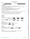
A. No Charge
Use standard evacuating techniques. After evacuating sys-
tem, weigh in the specified amount of refrigerant (refer to
Table 1).
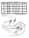
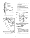
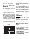
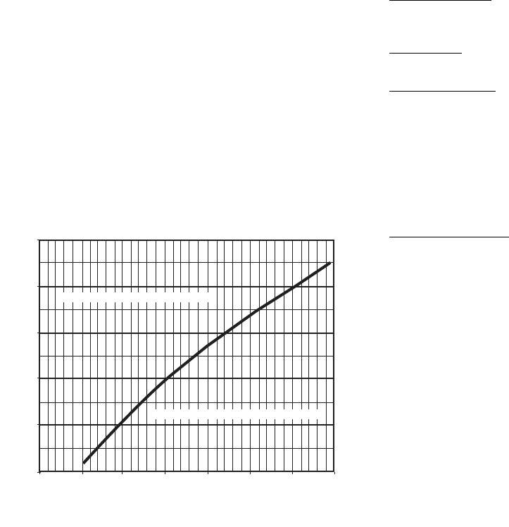
B. Low Charge Cooling
Using cooling charging chart (see Fig. 35), add or remove
refrigerant until conditions of the chart are met. Note that
charging chart is different from those normally used. An
accurate pressure gage and temperature-sensing device is
required. Charging is accomplished by ensuring the proper
amount of liquid subcooling. Measure liquid line pressure at
the liquid line service valve using pressure gage. Connect
temperature sensing device to the liquid line near the liquid
line service valve and insulate it so that outdoor ambient
temperature does not affect reading.
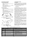
C. To Use The Cooling Charging Chart
Use the above temperature and pressure readings, and find
the intersection point on the cooling charging chart. If inter-
section point on chart is above line, add refrigerant. If inter-
section point on chart is below line, carefully recover some of
the charge. Recheck suction pressure as charge is adjusted.
NOTE: Indoor-air CFM must be within normal operating
range of unit. All outdoor fans must be operating.
The TXV (thermostatic expansion valve) is set to main-
tain between 15 and 20 degrees of superheat at the compres-
sors. The valves are factory set and should not require
re-adjustment.
D. Perfect Humidity™ System Charging
The system charge for units with the Perfect Humidity
option is greater than that of the standard unit alone. The
charge for units with this option is indicated on the unit
nameplate drawing. To charge systems using the Perfect
Humidity Dehumidification package, fully evacuate, recover,
and re-charge the system to the nameplate specified charge
level. To check or adjust refrigerant charge on systems using
the Perfect Humidity Dehumidification package, charge per
the standard subcooling charts. The subcooler MUST be
deenergized to use the charging charts. The charts reference
a liquid pressure (psig) and temperature at a point between
the condenser coil and the subcooler coil. A tap is provided
on the unit to measure liquid pressure entering the sub-
cooler (leaving the condenser).
X. FILTER DRIER
Replace whenever refrigerant system is exposed to
atmosphere.
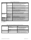
XI. PROTECTIVE DEVICES
A. Compressor Protection
Overtemperature
Each compressor has an internal protector to protect it
against excessively high discharge gas temperatures.
Overcurrent
Each compressor has internal line break motor protection.
Crankcase Heater
All units are equipped with a 70-watt crankcase heater to
prevent absorption of liquid refrigerant by oil in the crank-
case when the compressor is idle. The crankcase heater is
energized whenever there is a main power to the unit and
the compressor is not energized.
IMPORTANT: After prolonged shutdown or servicing, ener-
gize the crankcase heaters for 24 hours before starting the
compressors.
Compressor Lockout
If any of the safeties (high-pressure, low-pressure, freeze
protection thermostat, compressor internal thermostat) trip,
or if there is loss of power to the compressors, the CLO (com-
pressor lockout) will lock the compressors off. To reset, man-
ually move the thermostat setting.
B. Evaporator Fan Motor Protection
A manual reset, calibrated trip, magnetic circuit breaker
protects against overcurrent. Do not bypass connections or
increase the size of the breaker to correct trouble. Determine
the cause and correct it before resetting the breaker.
C. Condenser-Fan Motor Protection
Each condenser-fan motor is internally protected against
overtemperature.
D. High- and Low-Pressure Switches
If either switch trips, or if the compressor overtemperature
switch activates, that refrigerant circuit will be automati-
cally locked out by the CLO. To reset, manually move the
thermostat setting.
50
40
100
150
200
250
300
350
400
60
80
100
120
140
ALL OUTDOOR FANS MUST BE OPERATING
LIQUID PRESSURE AT LIQUID VALVE (PSIG)
LIQUID TEMPERATURE AT LIQUID VALVE (DEG F)
BOTH CIRCUITS
REDUCE CHARGE IF BELOW CURVE
ADD CHARGE IF ABOVE CURVE
Fig. 35 — Cooling Charging Chart