


—
16
—
Install Motormaster® I Controls
Only one Motormaster I control is required per unit. The
Motormaster I control must be used in conjunction with the
Accessory 0° F Low Ambient Kit (purchased separately). The
Motormaster I device controls outdoor fan no. 1 while out-
door fans no. 2 and 3 are sequenced off by the Accessory 0° F
Low Ambient Kit.
Accessory 0° F Low Ambient Kit — Install the Accessory 0° F
Low Ambient Kit per instruction supplied with accessory.
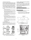
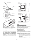
Sensor Assembly — Install the sensor assembly in the loca-
tion shown in Fig. 26.
Motor Mount — To ensure proper fan height, replace the
existing motor mount with the new motor mount provided
with accessory.
Transformer (460-v Units Only) — On 460-volt units a trans-
former is required. The transformer is provided with the
accessory and must be field-installed.
Motormaster I Control — Recommended mounting location
is on the inside of the panel to the left of the control box. The
control should be mounted on the inside of the panel, verti-
cally, with leads protruding from bottom of extrusion.
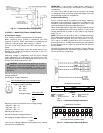
B. Motormaster III Control Installation (551A240 Only)
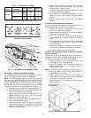
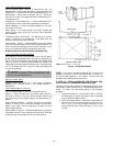
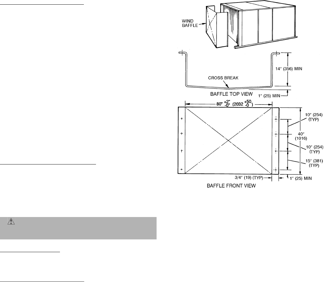
Install Field-Fabricated Wind Baffles
Wind baffles must be field-fabricated for all units to ensure
proper cooling cycle operation at low ambient temperatures.
See Fig. 25 for baffle details. Use 20-gage, galvanized sheet
metal, or similar corrosion-resistant metal for baffles. Use
field-supplied screws to attach baffles to unit. Screws should
be
1
/
4
-in. diameter and
5
/
8
-in. long. Drill required screw holes
for mounting baffles.
Replace Outdoor Motor
Replace outdoor fan motor no. 1 with motor included in
accessory kit. Existing motor is not Motormaster® III
compatible.
Install Motormaster III Controls
Only one Motormaster III control is required per unit.
Sensor — Install the sensor for thermistor input control in
the location shown in Fig. 26. Connect sensor leads to the
purple and grey control signal leads on the Motormaster III
control.
Signal Selection Switch — Remove the cover of the Motor-
master III control. Set the switch to accept the thermistor
sensor input signal. Set the frequency to match the unit
power supply (60 Hz).
Motormaster III Control — Recommended mounting location
is beneath the control box, mounted to the partition that sep-
arates the control box section from the indoor section.
NOTE: If unit power is supplied through the roof curb and
basepan of the unit, mount the Motormaster III control on
the corner post adjacent to the conduit running from the
basepan to the bottom of the control box.
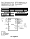
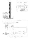
X. STEP 10 — INSTALL HUMIDISTAT FOR OPTIONAL PER-
FECT HUMIDITY™ DEHUMIDIFICATION PACKAGE
Perfect Humidity dehumidification package operation can be
controlled by field installation of a Bryant-approved humi-
distat. To install the humidistat perform the following
procedure:
1. Locate humidistat on a solid interior wall in the con-
ditioned space. Location should be a well ventilated
area to sense average humidity.
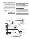
2. Route thermostat cable or equivalent single leads of
colored wire from humidistat terminals through con-
duit in unit to the low voltage connection on the
2-pole terminal strip (TB3) as shown in Fig. 27 and
Fig. 28.
CAUTION:
To avoid damage to the refrigerant coils
and electrical components, use recommended screw sizes
only. Use care when drilling holes.
NOTE:
Dimensions in ( ) are in mm.
Fig. 25 — Wind Baffle Details