


—
15
—
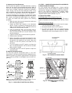
H. Ventilation Air (Minimum Position Set Up)
If ventilation air is not required, skip this section. If ventila-
tion air is required, perform the following:
1. The indoor fan must be on to set the ventilation air.
Either put the thermostat in the continuous fan mode
or jumper the R and G terminals at the rooftop unit
connection board.
2. Locate the minimum position (MIN POS) potentiome-
ter. Turn the potentiometer full CCW to fully close
the outdoor air dampers. Turn the potentiometer
gradually clockwise (CW) to the desired position. See
Fig. 16.
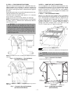
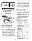
3. Replace the filter access panel. See Fig. 18. Ensure
the filter access panel is securely engaged.
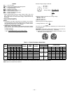
4. Calculate the minimum airflow across the
EconoMi$er.
a. Calculate % of outside air using the following
formula.
% Outdoor air through EconoMi$er
b. Multiply total CFM by percentage outdoor air,
this gives outdoor air volume in CFM.
IX. STEP 9 — INSTALL ALL ACCESSORIES
After all the factory-installed options have been adjusted,
install all field-installed accessories. Refer to the accessory
installation instructions included with each accessory.
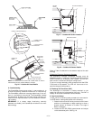
A. Motormaster® I Control Installation (551A155 and 180
Only)
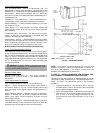
Install Field-Fabricated Wind Baffles
Wind baffles must be field-fabricated for all units to ensure
proper cooling cycle operation at low ambient temperatures.
See Fig. 25 for baffle details. Use 20-gage, galvanized sheet
metal, or similar corrosion-resistant metal for baffles. Use
field-supplied screws to attach baffles to unit. Screws should
be
1
/
4
-in. diameter and
5
/
8
-in. long. Drill required screw holes
for mounting baffles.
% Outdoor
air
=
Mixture Temp – Return Air Temp
Outdoor Temp – Return Air Temp
WARNING:
Personal Injury Hazard.
Avoid possible
injury by keeping fingers away from damper blades.
CAUTION:
To avoid damage to the refrigerant coils
and electrical components, use recommended screw sizes
only. Use care when drilling holes.
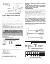
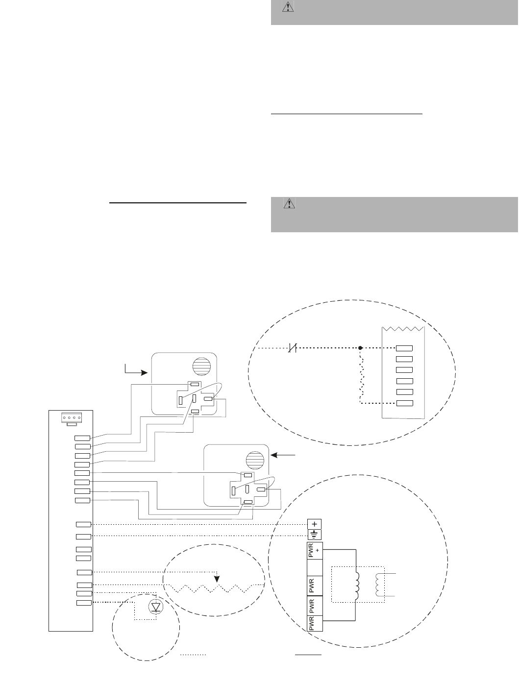
20 mA LED
1k ohm Potentiometer
2to10VDCat
0 to 2000 ppm
CO2 Sensors:
Remote
Minimum Position
Remote
LED
Outdoor Air Enthalpy
CROUTENT001A00
Return Air Enthalpy
CRRETENT001A00
Line
Voltage
CO
CO
COM
DAT
COM
REM
POT
COM
LED
COM
2
2
OAT
COM
OAH
+15V
RAT
COM
RAH
+15V
C
O
M
PW
O
U
TT
T
Violet
C
O
M
PW
O
U
T
T
T
Violet
Field-supplied Wiring Wiring Included
470 ohm
5watt
Resistor
24 VAC must be present
on BI for the system to be
unoccupied.
Unoccupied Control
(Part number on the control
must be AD-DME1701-1
or AD-DME1711-1.)
Unoccupied
Contact
Tan
Violet
White
Red
Tan
Violet
White
Red
24 VAC
20 VA
NOT
USED
1
2
-
(+)
CRCDXSEN004A00
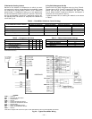
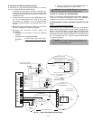
Fig. 24 — Typical EconoMi$er Sensor Wiring