


—
4
—
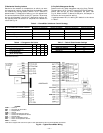
UNIT
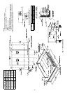
551A
STD UNIT
WEIGHT
ECONOMI$ER
WEIGHT
CORNER
A
CORNER
B
CORNER
C
CORNER
D
DIM A DIM B DIM C
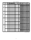
Lb Kg Lb Kg Lb Kg Lb Kg Lb Kg Lb Kg ft-in. mm ft-in. mm ft-in. mm
155
1575 714 80 36.3 407 185 375 170 383 174 410 186 3-5 1039 3-5 1054 1-10 559
180
1650 748 80 36.3 375 170 375 170 449 204 452 205 3-2 963 3-7 1092 1-10 559
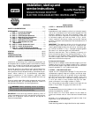
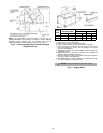
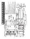
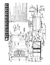
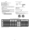
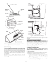
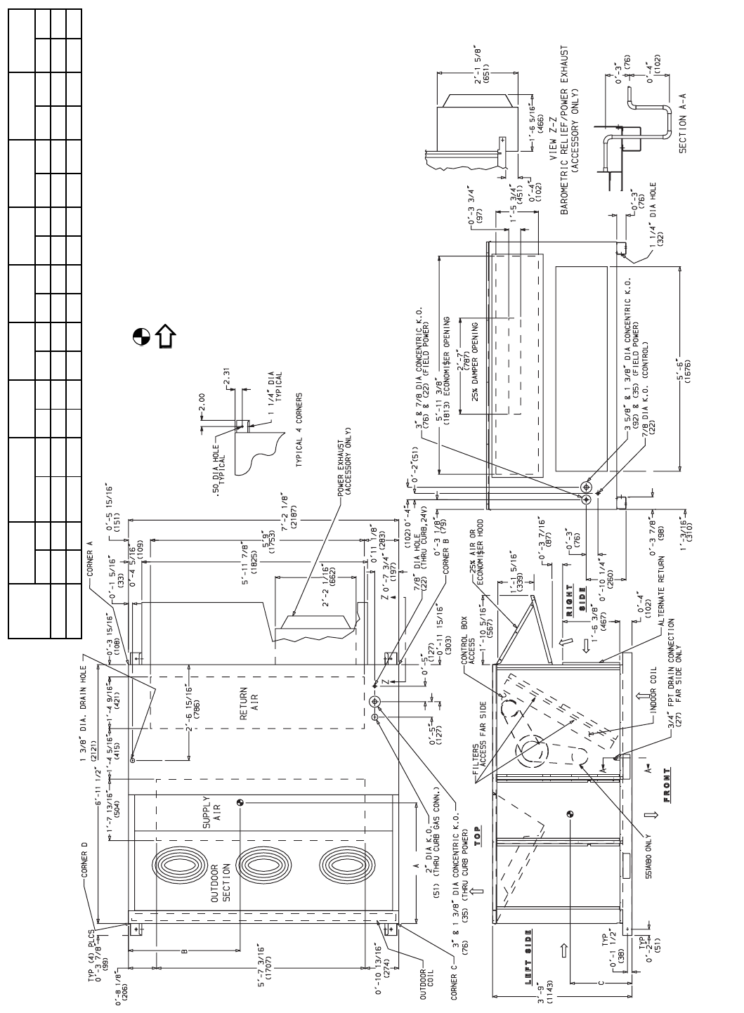
Fig. 4 — Base Unit Dimensions, 551A155 and 180
NOTES:
1. Refer to print for roof curb accessory dimensions.
2. Dimensions in ( ) are in millimeters.
3. Center of Gravity.
4. Direction of airflow.
5. Ductwork to be attached to accessory roof curb only.
6. Minimum clearance:
• Rear: 7
′
-0
″
(2134) for coil removal. This dimension can be reduced to
4
′
-0
″
(1219) if conditions permit coil removal from the top.
• Left side: 4
′
-0
″
(1219) for proper condenser coil airflow.
• Front: 4
′
-0
″
(1219) for control box access.
• Right side: 4
′
-0
″
(1219) for proper operation of damper and power
exhaust if so equipped.
• Top: 6
′
-0
″
(1829) to assure proper condenser fan operation.
• Local codes or jurisdiction may prevail.
7. With the exception of clearance for the condenser coil and the
damper/ power exhaust as stated in Note #6, a removable fence or
barricade requires no clearance.
8. Dimensions are from outside of corner post. Allow 0
′
-
5
/
16
″
(8) on each
side for top cover drip edge.
9. See drawing 50TJ500352 for service option details.
10.
A
90 degree elbow must be installed on the supply ductwork
below the unit discharge for units equipped with electric heaters.